In the Logical Architecture stage we focus on the system, its components and functions.
The explanation in the Workflow window is as follows:
See the system as a white box: define how the system will work so as to fulfill expectations
Perform a first trade-off analysis
Recall that our system, Toy Catapult, is considered as a black box in the previous stage;
and now, we are ready to define its subsystems.
Then, we will map the functions to these subsystems.
Finally, we will refine the system functions, as required, considering the functional interchanges among the system components.
We carry out our behavioral analysis at this phase and define the subsystems.
A subsystem (or a component) is a collection of elements of a system that has an identifiable function of its own.
Defining components and their interfaces also helps in splitting the design tasks into subtasks to be assigned to different development teams.
It is out of the scope of this tutorial to detail an approach for identifying the subsystems of a system.
There are, in fact, at least three separate approaches one could use:
If one has a list of components typically used in similar designs, one can group these components according
to the degree of interaction among them: (a) highly interconnected components belong within the same subsystem
and (b) subsystems should have minimal and well-defined interactions with each other.
Alternatively, one can start
with high level functional requirements and organize the subsystems around major functionalities of the system.
Yet another approach is to divide up the system according to the skillsets of existing teams (mechanical, electrical, computing, etc.).
Recall from the System Analysis phase for our toy catapult project, we used an affinity technique
and identified four high-level system functions: Arm, Load, Fire, and Launch.
Let's organize subsystems around these major functionalities.
Energy Storage
Projectile Containment
Lock and Release
Launch
The system shall store and release energy
The system shall hold the projectile until launch
The system shall detect commands to lock and release energy
The system shall convert energy to translational energy and propel the projectile
Next, we revisit our scenarios.
Recall that we have two operational scenarios: Child Plays and Parent Teaches,
with corresponding functional chains
Single Shot and Train Shot.
In this phase, we will refine these scenarios considering the subsystems and the interactions among them.
Furthermore, we will define the states or modes of the system, and define which functions are available in which modes.
We will not be defining new actors or capabilities in this phase.
(If these were required, we would need to go back and revise the earlier phases of our design.)
We will use the transition feature of Capella to carry elements forward.
Transition of System Actors
In the following step, we will perform the transition of the System Actors to Logical Actors.
Click Perform an automated transition of System Actors in the Logical Architecture tab of the workflow.
Click Apply in the Actor Transition dialog; and click OK in the pop-up dialog to confirm the action.
The transition will be performed.
Let us check the model elements in Capella Project Explorer.
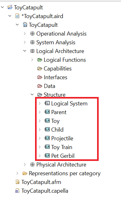
Expand the folder
ToyCatapult.aird → ToyCatapult → Logical Architecture → Structure.
You will see that our system actors Child, Parent, Projectile and Toy Train
are realized as logical actors.
Recall that a lot of things happen during transitions from previous design phases.
In this transition, functions defined in the System Analysis phase are also transferred as logical functions together with defined
actor allocations.
In order to observe the transferred functions,
expand the folder
ToyCatapult.aird → ToyCatapult → Logical Architecture → Logical Functions → Root Logical Function.
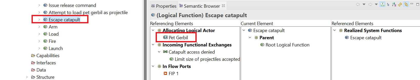
In order to check whether the allocations are also transferred,
(1) select the logical function Escape catapult in the project explorer, and
(2) open the Semantic Browser tab at the bottom window.
(3) You will observe that this function realized the system function with the same name.
(4) You will also notice that the function is already allocated to the logical actor Pet gerbil.
(5) Finally, observe that the functional exchanges have also been transferred from the previous design phase.
Many of these logical functions which realize system functions can be left as they are. But, some will need to be refined.
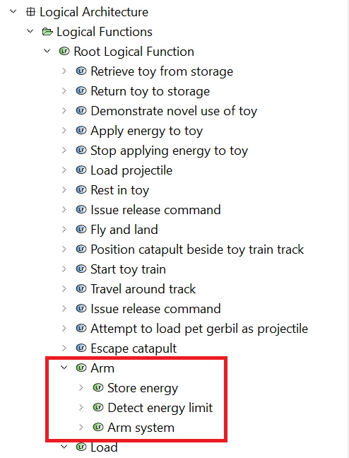
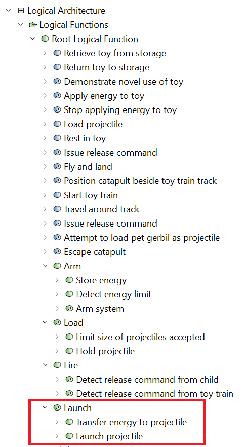
We observe that there were errors in the automated transition. The system function Detect energy limit did not give rise to a logical function of the same name.
It should appear as a sub-function of the Arm function.
Also, the system function Transfer energy to projectile did not give rise to a logical function of the same name.
It should appear as a sub-function of the Launch function.
Fortunately, we can force these transitions to occur. If these errors did not occur in your model, then skip the next steps.
In the Project Explorer, navigate to ToyCatapult.aird → ToyCatapult → System Analysis →
System Functions → Root System Function → Arm → Detect energy limit.
Right-click on this entry and select Transitions → Functional Transition.
Click Apply in the Functional Transition dialog.
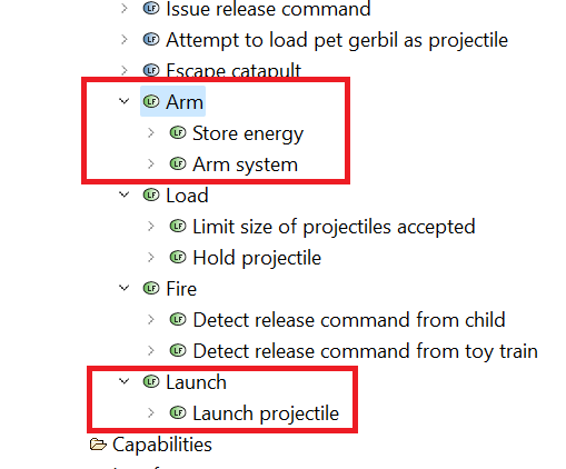
The transition will be performed. Confirm by checking the logical function Arm again.
This corrects one of the errors in transition: Detect energy limit is now a logical function as well.
Repeat the previous step but this time applied to ToyCatapult.aird → ToyCatapult → System Analysis →
System Functions → Root System Function → Launch → Transfer energy to projectile.
This corrects the remaining error in transition: Transfer energy to projectile is now a logical function as well.
Transition of Capabilities
Now let us perform the transition of the capabilities.
Note that we will require capabilities for defining our revised scenarios; each scenario must be related to a capability.
Furthermore, we must make sure that none of the capabilities defined in earlier stages are ignored, and all are realized at this phase.
Click Perform an automated transition of System Analysis Capabilities in the Logical Architecture tab of the workflow.
Click Apply in the capability transition dialog; and click OK in the popup dialog to confirm the transition.
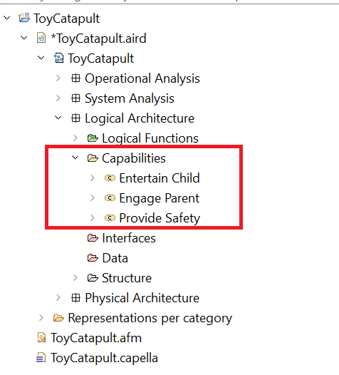
In order to observe that the capabilities are transferred, expand the folder
ToyCatapult.aird → ToyCatapult → Logical Architecture → Capabilities.
As we have performed all the necessary transitions from the previous phase, we are ready to define our subsystems in Capella.
Capella uses the term "Component" for what we would call "Subsystem" or "Module". We will use that terminology for the rest of
the tutorial.
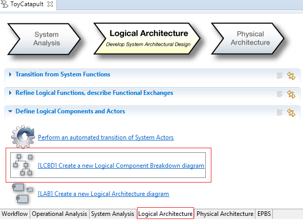
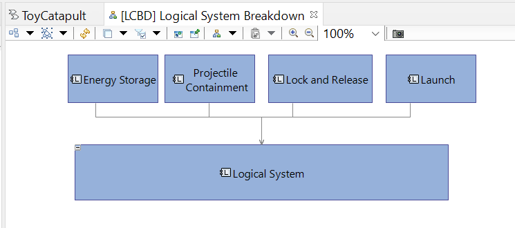
Click [LCBD] Create a new Logical Component Breakdown diagram in the
Logical Architecture tab of the workflow.
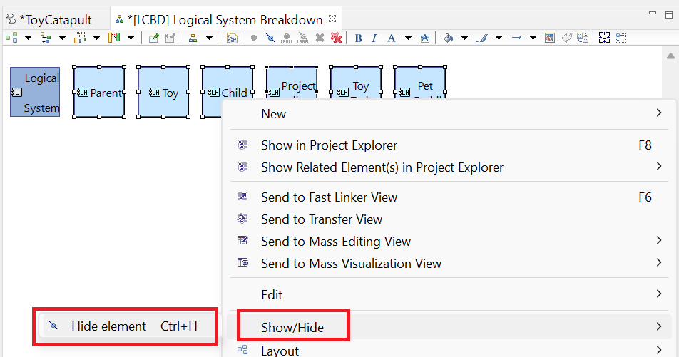
The LCBD diagram is created with all logical actors added to it automatically. Select all logical actors except the Logical System and hide them from the diagram (deleting them from the diagram is not an option).
Use the Logical Component tool in the Palette to create four components attached to the Logical System actor:
Energy Storage, Projectile Containment, Lock and Release, and Launch. The components are shown outside the Logical System with "contained in" arrows pointing to the Logical System.
Save and close the diagram.
In the System Analysis tutorial we conducted scenario analysis by going back and forth between architectural views,
where we created and allocated functions to actors, and exchange scenario diagrams where we defined interactions between functions. In this phase, Logical Architecture,
most of the functions and exchange interactions have already been defined (transitioned from the System Analysis phase).
The main task we have is to allocate our system functions to the components of the logical architecture. We will do this primarily with architecture views,
creating what some people refer to as "activity diagrams with swimlanes," though Capella doesn't use that terminology.
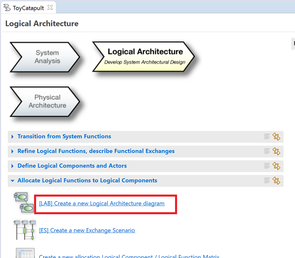
Click [LCBD] Create a new Logical Architecture diagram in the
Logical Architecture tab of the workflow.
Name the new diagram [LAB] Logical Architecture View of Child Plays Scenario.
Use the Actors and Components tools in the Palette to add the
Child and Projectile actors as well as the Logical System and all its components to the diagram. Re-size the boxes as shown below.
Use the Manage Functional Allocation tool in the Palette to add the Store energy
function to the Energy Storage component block.
Continue using the Manage Functional Allocation tool to make the following allocations:
Detect energy limit to Lock and release
Arm system to Lock and release
Detect release command from child to Lock and release
Hold projectile to Projectile Containment
Limit size of projectiles accepted to Projectile Containment
Transfer energy to projectile to Launch
Launch projectile to Launch
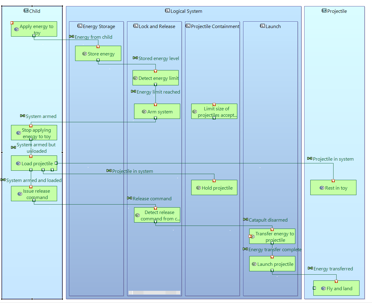
Use styling techniques from the System Analysis tutorial to arrange the functions and ports as follows:
Use the Allocated Functions tool to add the following functions to the Child block:
Apply energy to toy
Stop applying energy to toy
Load projectile
Issue release command
Similarly, use the Allocated Functions tool to add all available functions to the Projectile block.
Use styling techniques from the System Analysis tutorial to arrange the functions and ports as follows:
The main thing accomplished here was to allocate system functions to particular components. To illustrate that we can continue to flesh out
our functional view of the system using the architecture diagram, let's add a branch to the scenario we are describing: It is possible that the
child could abandon the toy before it is fully armed. In that case, the energy would be prematurely released and it would return to its unarmed state.
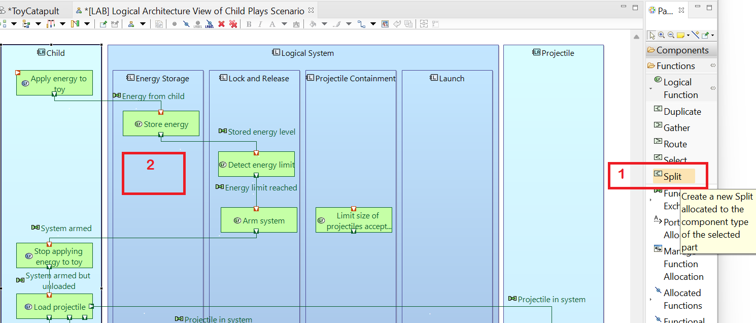
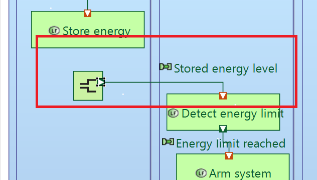
(1) Click the Split tool (in the Functions section of the Palette) and
(2) click in the Energy Storage block to add a Split function.
Drag the out port of the Stored energy level functional exchange
from the Store energy function and reattach it to the Split function.
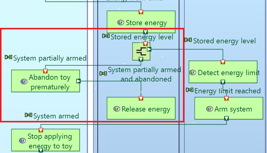
Use the Logical Function tool to add a function, Abandon toy prematurely, to the Child
block and another function, Release energy, to the Energy Storage block.
Use the Functional Exchange tool to add the following functional exchange connections:
From Store energy to Split, named Stored energy level
From Split to Abandon toy prematurely, named System partially armed
From Abandon toy prematurely to Release energy, named System partially armed and abandoned
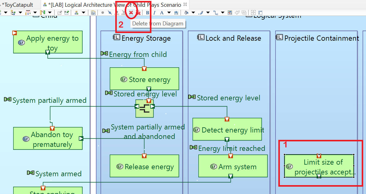
Since this diagram is supposed to be an architectural view of the Child Plays scenario, it doesn't make sense to include
the function Limit size of projectiles accepted. (1) Click on this function and (2) click the Delete From Diagram
menu button.
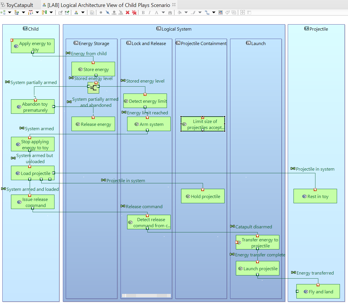
The final view of this diagram should look like this:
You may close the diagram now.
The diagram we have just created, [LAB] Logical Architecture View of Child Plays Scenario, is in a style which could be called
"activity diagram with swimlanes."
Each vertical block is a swimlane for the associated actor or component, similar to a timeline in an exchange scenario diagram. The functions represent activities performed by
that actor or component as part of the use case or scenario. Any functional exchange connector that crosses from one swimlane to another represents an interface between
two components or actors or component-actor pairs. Let's create a similar activity diagram with swimlanes to describe the Parent teaches scenario. We can take advantage of
the work we have already done by cloning the [LAB] Logical Architecture View of Child Plays Scenario diagram.
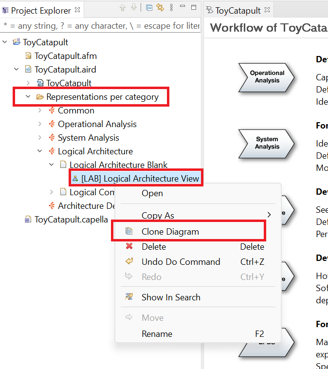
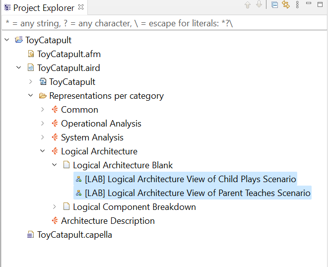
Use the Project Explorer to navigate to the entry for [LAB] Logical Architecture View of Child Plays Scenario.
It is in the ToyCatapult.aird → Representations per Category → Logical Architecture → Logical Architecture Blank folder.
Right-click on the entry and choose Clone Diagram.
Right-click on the entry for the cloned file, choose Rename and rename it as
[LAB] Logical Architecture View of Parent Teaches Scenario. Then double-click the entry to open the new diagram.
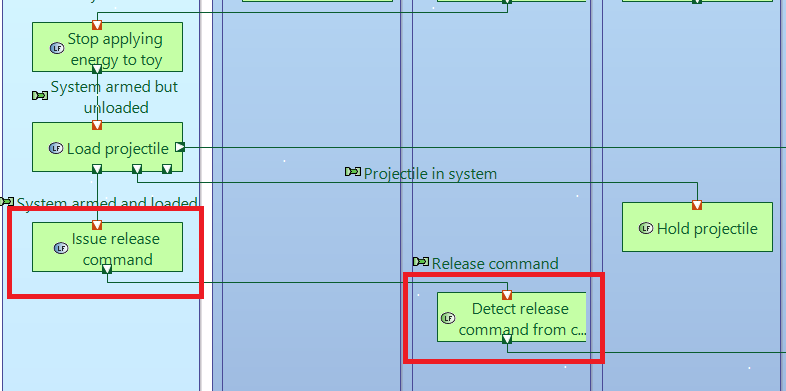
Two functions need to be removed from the diagram for this view. Select the Issue release command
and Detect release command from child functions and click
Delete From Diagram in the menu. (Alternatively, right-click one of the selected functions and choose Edit → Delete From Diagram.)
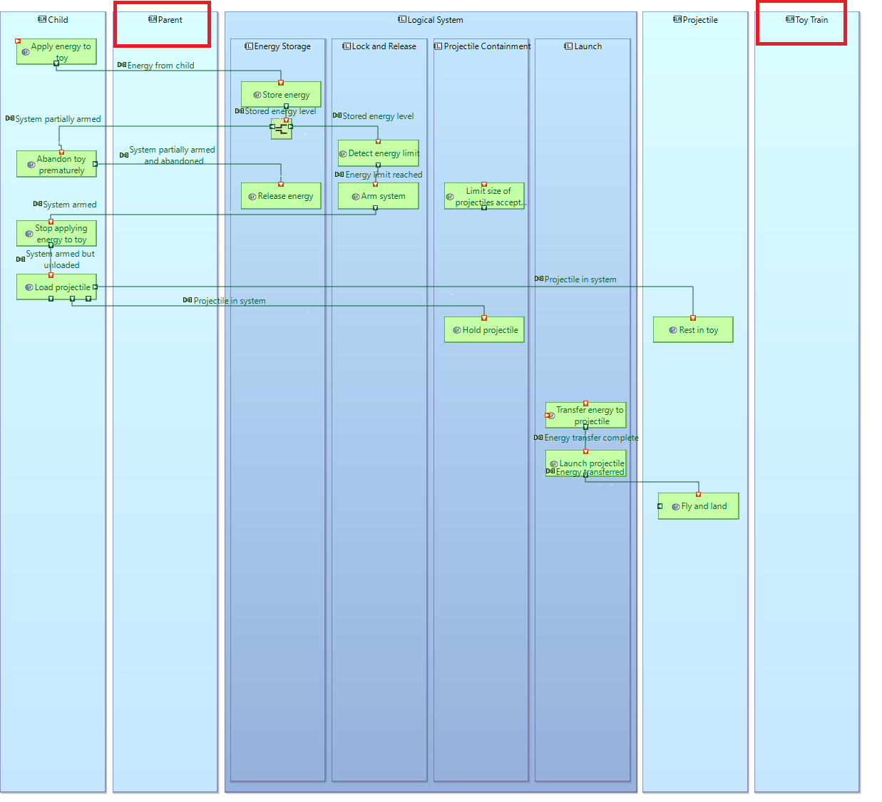
Double-click on the tab for the window to maximize the view and zoom out to have a larger working area. Use the Actors
tool in the Palette to add blocks for the Parent and Toy train. Arrange the blocks so that
Child and Parent blocks are to the left of the Logical Systems and the Projectile
and Toy train are to the right. Extend the vertical height of each box to accommodate some more functions.
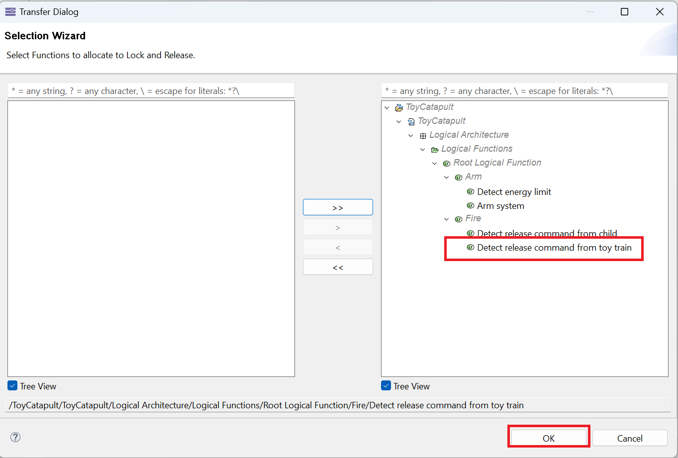
Click the Manage Function Allocation tool and click anywhere in the Lock and Release block. Ensure that
the Detect release command from toy train function has been allocated to this block. Click OK.
Use the Allocated Functions tool to add the Detect release command from toy train function to the diagram
in the Lock and Release block. Fix the formats to match the style of the rest of the diagram.
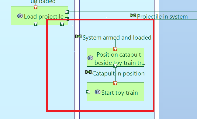
Use the Allocated Functions tool to add the Position catapult beside toy train track and
Start toy train functions in the Parent block. Fix the formats.
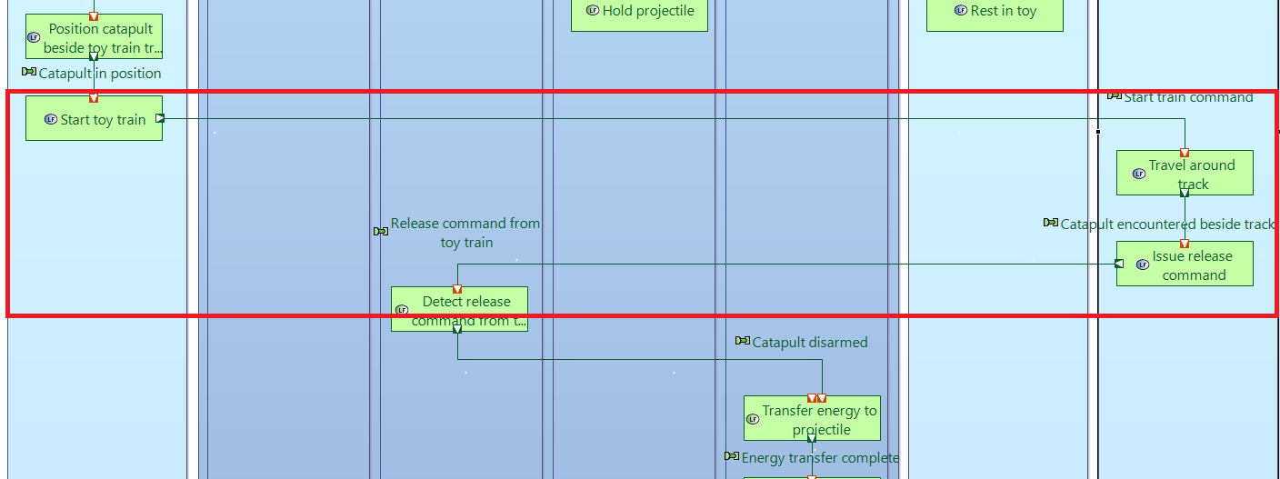
Use the Allocated Functions tool to add the Travel around track and
Issue release command functions in the Toy train block. Fix the formats.
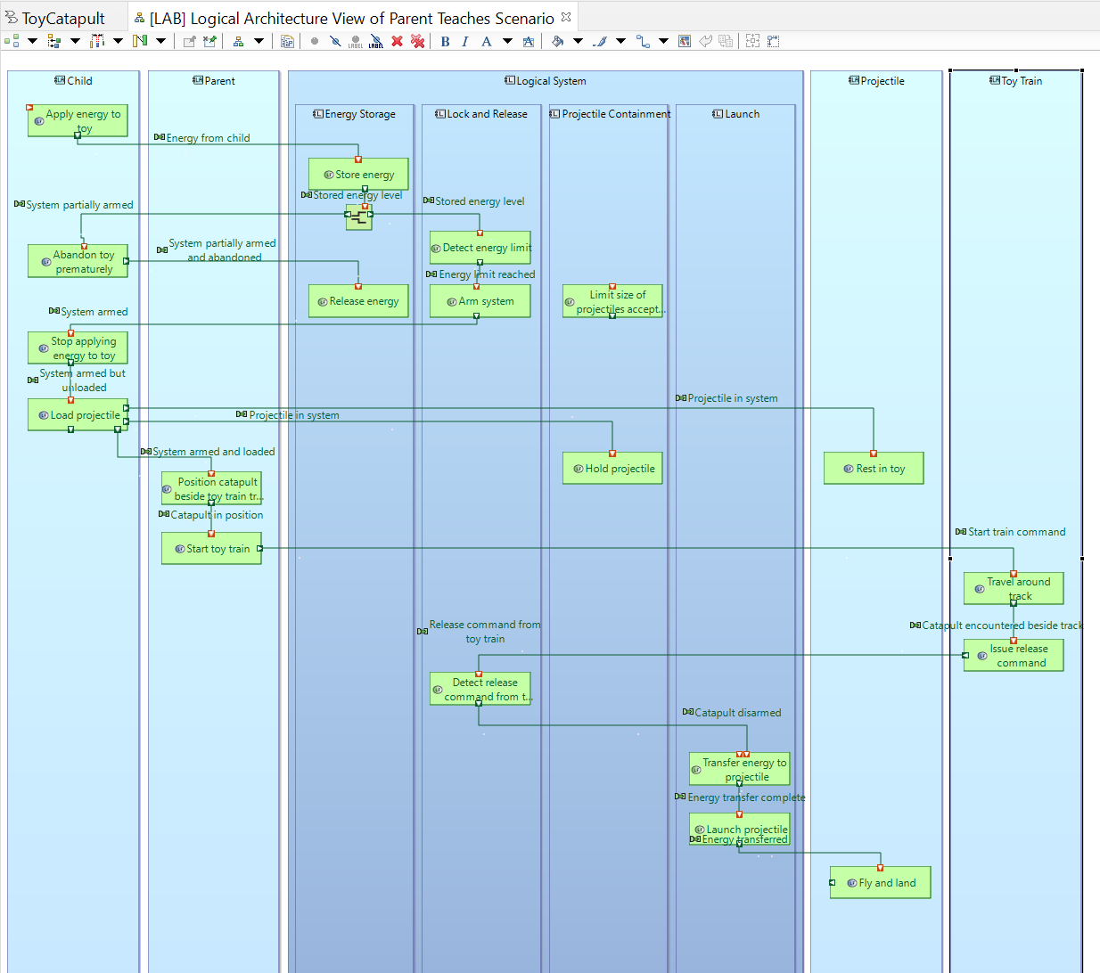
The completed [LAB] Logical Architecture View of Child Plays Scenario looks like this:
You may close this diagram.
In the previous sections, we have defined all logical functions and functional exchanges.
They are sufficient to define our functional chains derived from user scenarios. We have also created architectural views that make the
sequence of functions for each scenario, Child plays and Parent teaches, quite easy to see.
We will take advantage of each of these views to define our two functional chains, Single Shot Functional Chain and
Train Shot Functional Chain.
Use the Project Explorer to navigate to the
ToyCatapult.aird → Representations per Category → Logical Architecture → Logical Architecture Blank folder.
Double-click on each of the two entries in the folder to open the corresponding diagrams.
Activate the [LAB] Logical Architecture View of Child Plays Scenario diagram.
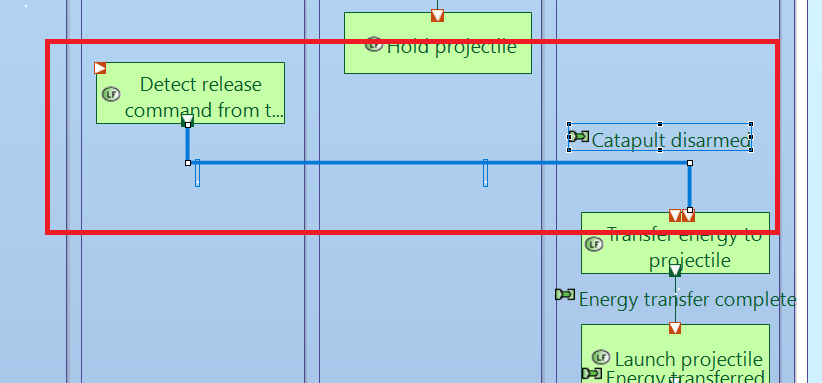
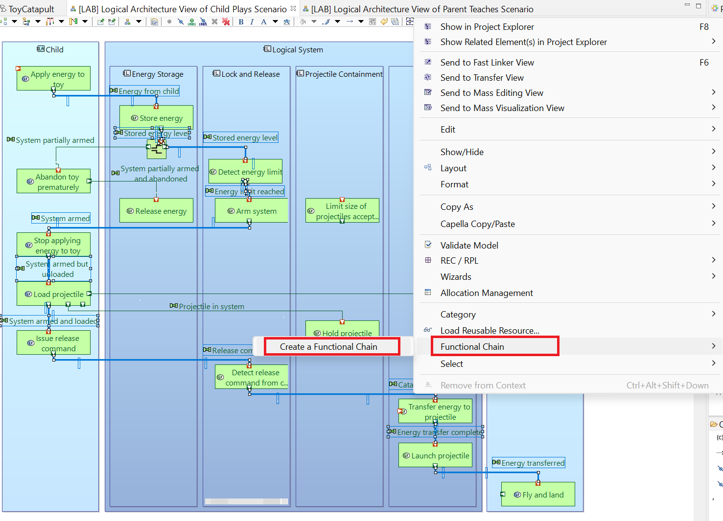
Holding down the Shift or Ctrl key, select all the functional exchanges on the path from Apply energy to toy to Fly and land, including the Split function.
Then, right-click on any of the selected functions and click Functional Chain → Create a Functional Chain.
(If the menu item Functional Chain does not appear, it is likely that you have not selected a complete path of functional exchanges.)
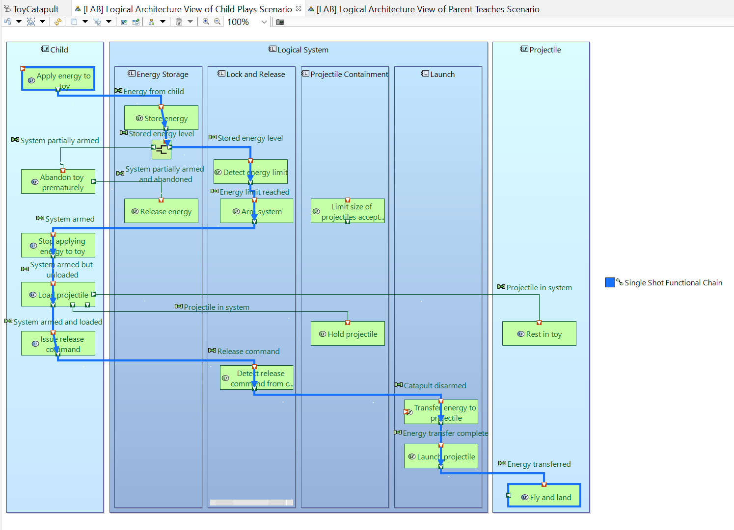
Rename the resulting functional chain as Single Shot Functional Chain.
Repeat the previous step using the [LAB] Logical Architecture View of Parent Teaches Scenario diagram. Rename the resulting
functional chain as Train Shot Functional Chain
You may close this diagram.
In this section, we will define the states (or modes) of our system.
There are at least two benefits of this type of analysis:
Firstly, we formally define which functionalities are or should be available in which modes.
Secondly, we may identify infinite loops of state changes which might be undesirable. We could then
design ways to escape the loops, if necessary.
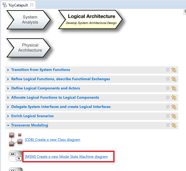
Click [MSM] Create a new Mode State Machine diagram in the
Logical Architecture of the workflow window.
The Selection dialog will pop up.
Observe that we could define the states of the entire system, of components, or even of the actors.
In this tutorial, we will define the states for our Logical System. Select the Logical System and click Ok.
Use the suggested name [MSM] Default Region or rename the diagram.
Your diagram with an empty working area will be created.
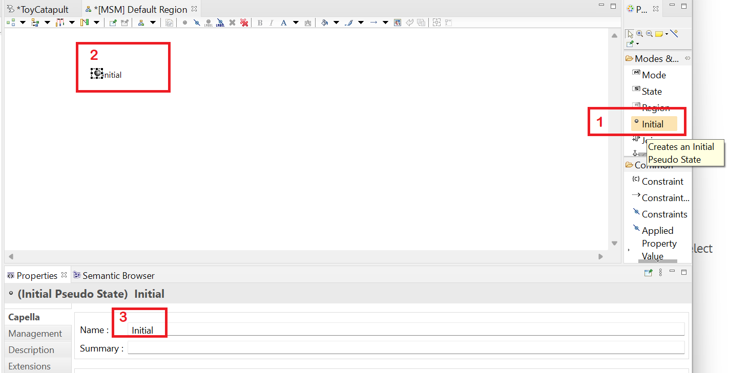
(1) Click on the Initial tool in the Palette,
(2) click anywhere in the working area to add the initial node, and
(3) rename the node as Initial.
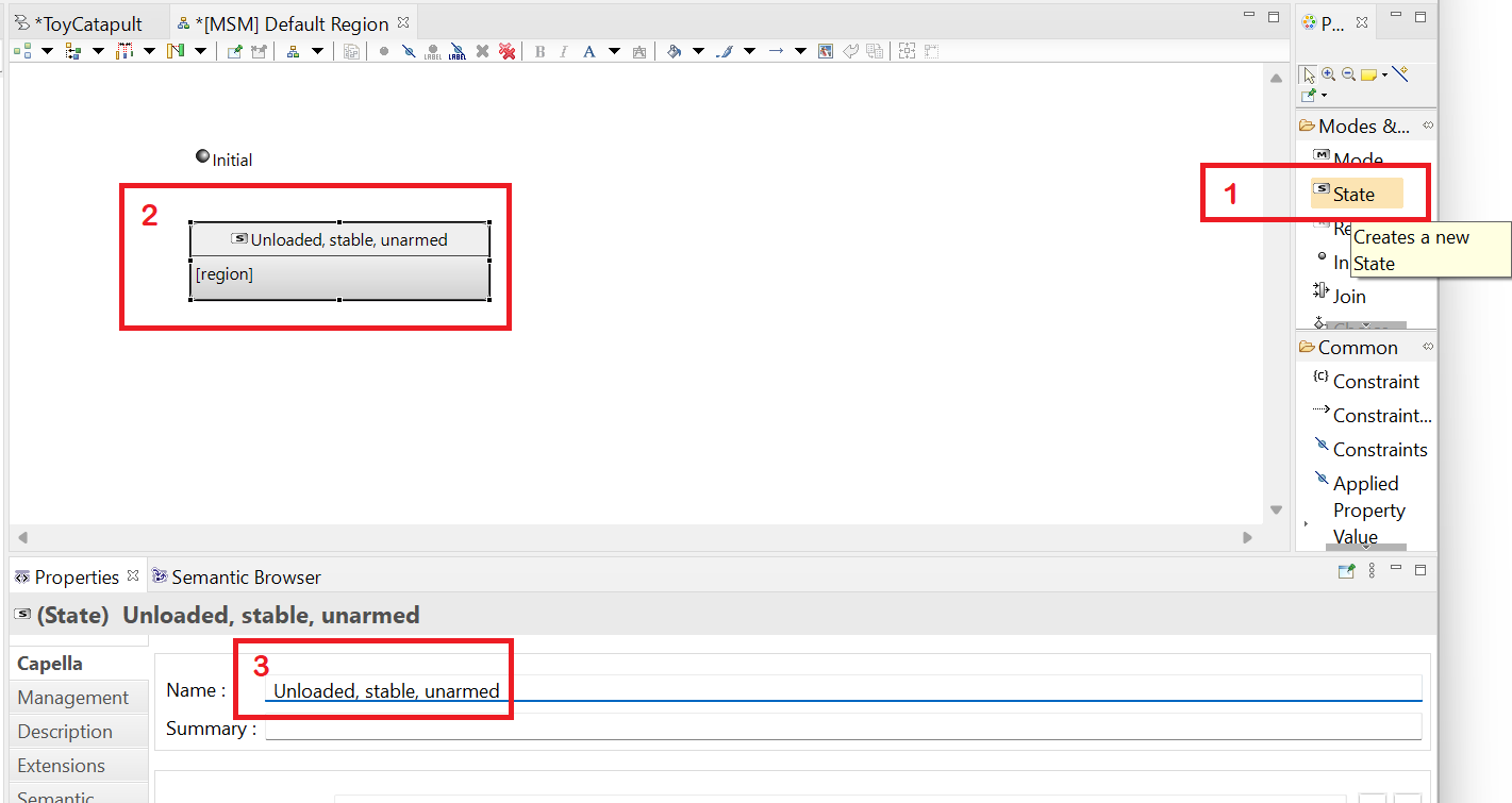
(System State) = (Unloaded, stable, unarmed)
(1) Click on the State tool in the Palette,
(2) click anywhere in the working area to add the state, and
(3) rename the node as Unloaded, stable, unarmed.
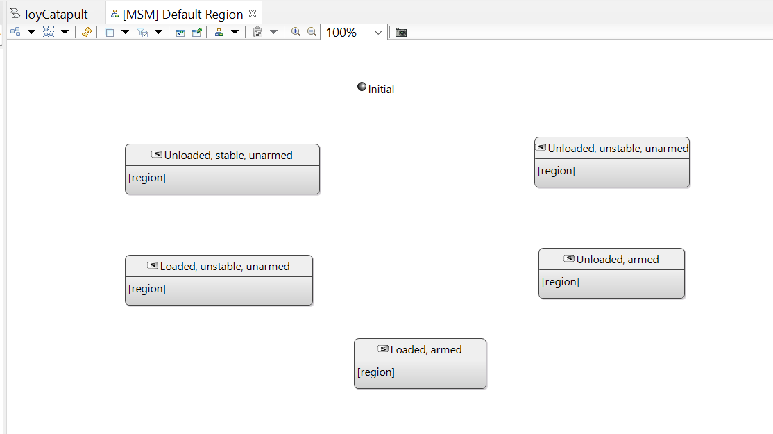
Repeat the previous step for the following system states:
Unloaded, unstable, unarmed
Unloaded, armed
Loaded, armed
Loaded, unstable, unarmed
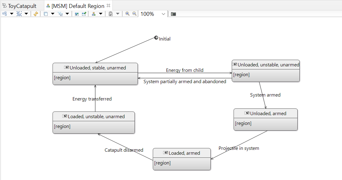
Finally, resize and reposition the states as shown in the following diagram.
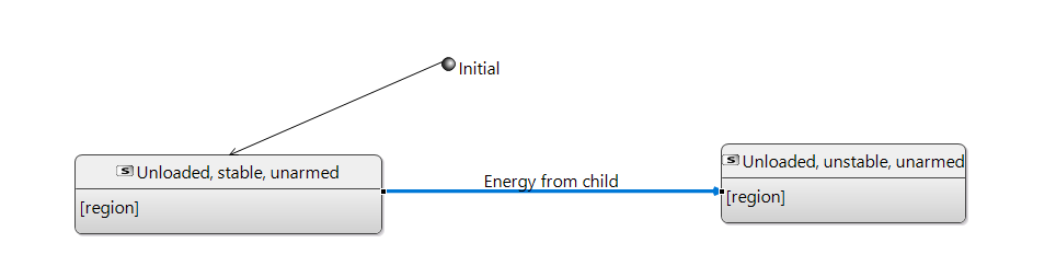
Firstly, we connect the initial node to the initial state Unloaded, stable, unarmed.
(1) Click on the Transition tool in the Palette,
(2) click the initial node, and
(3) click the Unloaded, stable, unarmed state.
The state transition (also known as a "state change") represented by an arc will be added.
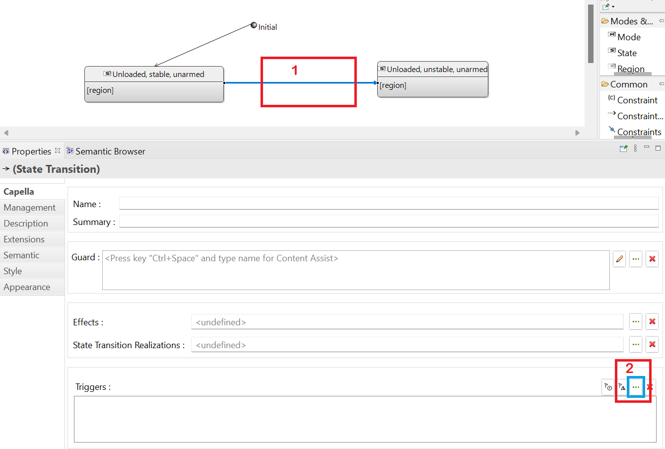
(From | To | Transition) = (Unloaded, stable, unarmed | Unloaded, unstable, unarmed | Energy from child)
(1) Click on the Transition tool in the Palette,
(2) click the from state Unloaded, stable, unarmed, and then
(3) click the to state Unloaded, unstable, unarmed.
The transition will be added.
State transitions should be defined using functions or functional exchanges.
In order to define when the transition happens,
(1) click on the transition arc, and
(2) click on the ... button next to the Triggers field in the Properties window.
The Transfer dialog will appear, displaying functions and functional exchanges which are relevant to the Logical System.
This transition happens with the Energy from child exchange.
Double-click to select the functional exchange and click OK.
The transition arc will be labelled with the name of the functional exchange.
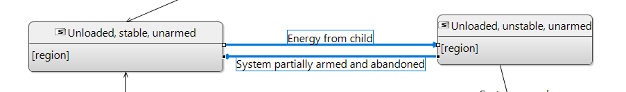
Repeat the previous step for the remaining transitions listed below in the form (From | To | Transition):
(Unloaded, unstable, unarmed | Unloaded, stable, unarmed | System partially armed and abandoned)
(Unloaded, unstable, unarmed | Unloaded, armed | Arm system)
(Unloaded, armed | Loaded, armed | Projectile in system)
(Loaded, unstable, unarmed | Unloaded, stable, unarmed | Energy transferred)
Your final state transition diagram should look like the following.
Using the state transition diagram, we can easily observe infinite loops.
For instance, we have the following infinite loop in our project.
It is a good practice to check such loops and decide whether we need to take preventive action.
This sequence of state transitions corresponds to a misfire and we conclude that this is not an undesirable behavior.
Although we will skip it in this tutorial, Capella allows us to specify the list of the functions that are available in each mode.
In order to illustrate,
(1) select the Unloaded, stable, unarmed state on the diagram, and
(2) click the ... button next to the Operational Activities / Functions field.
Double-click the Store energy function to select and click OK.
Note that you may select multiple functions in the transfer dialog.
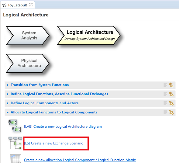
Following the Arcadia process, we should create scenarios to support each of the logical architecture capabilities. That would be quite tedious
for this tutorial, so we will skip that. However, simply to illustrate the steps, we offer the following optional exercise.
Click the [ES] Create a new Exchange Scenario button in the
Logical Architecture tab of the workflow.
Link it to the Provide safety capability:
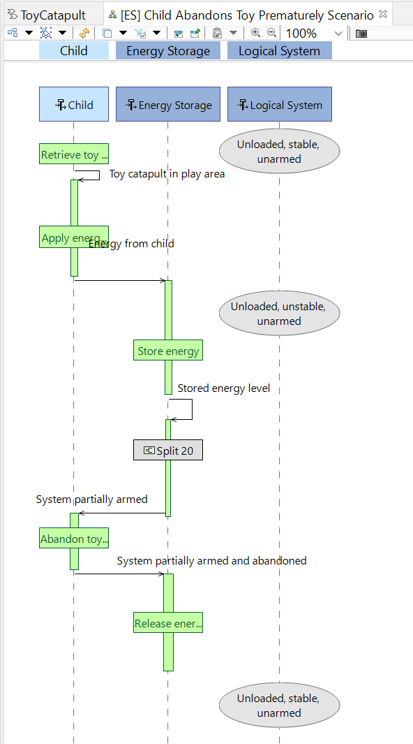
and name it [ES] Child Abandons Toy Prematurely Scenario.
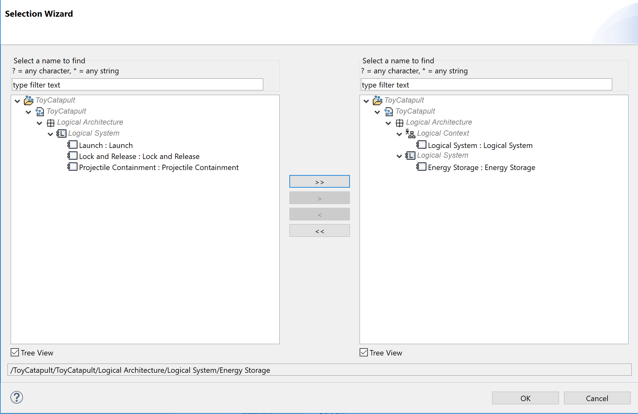
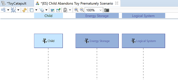
Using the Components tool, add timelines for the Logical System and the Energy Storage components.
Put the Logical System timeline on the far right.
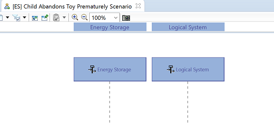
Using the Actors tool, add a timeline for the Child and place it on the left.
Use the Allocated Function tool to add the following state fragments.
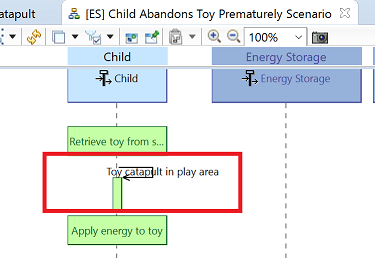
Use the Functional Exchange tool to add the existing exchange Toy catapult in play area.
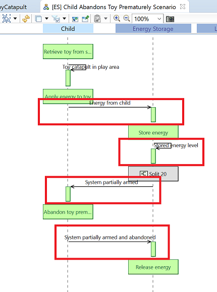
Similarly, add the remaining existing functional exchanges as shown in this diagram:
Adjust the formatting:
We attached this simple scenario to the Provides safety capability because it is a scenario that should be tested to ensure
the toy safely releases its energy in the case where the child abandons it before completely arming it.
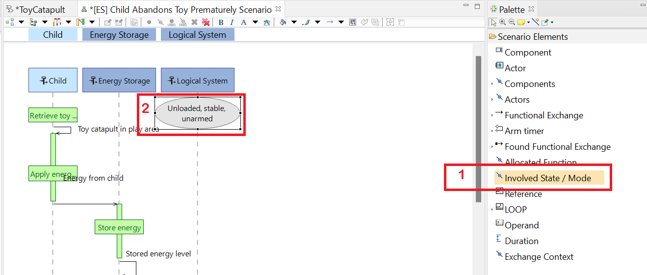
We use this simple scenario to illustrate one more feature of exchange scenarios: we can label them with system states.
(1) Click the Involved State / Mode tool and (2) click on the Logical System timeline. Select the state
Unloaded, stable, unarmed from the transfer dialog and click OK.
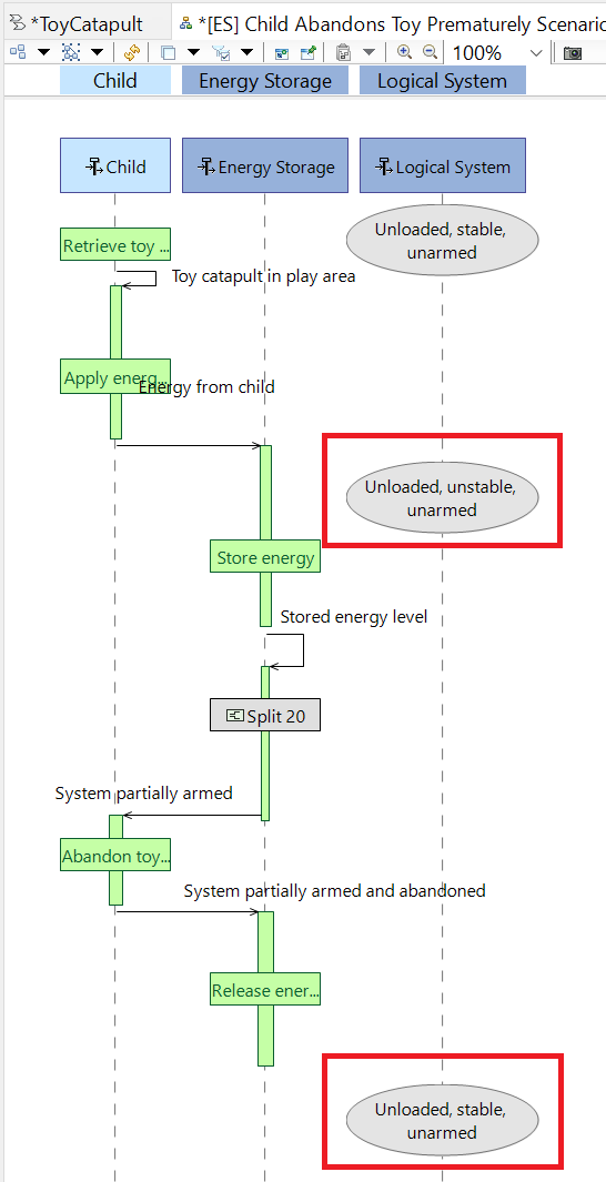
Repeat the previous step adding states Unloaded, unstable, unarmed and Unloaded, stable, unarmed as shown.
The completed scenario looks like this:
8. Logical Architecture
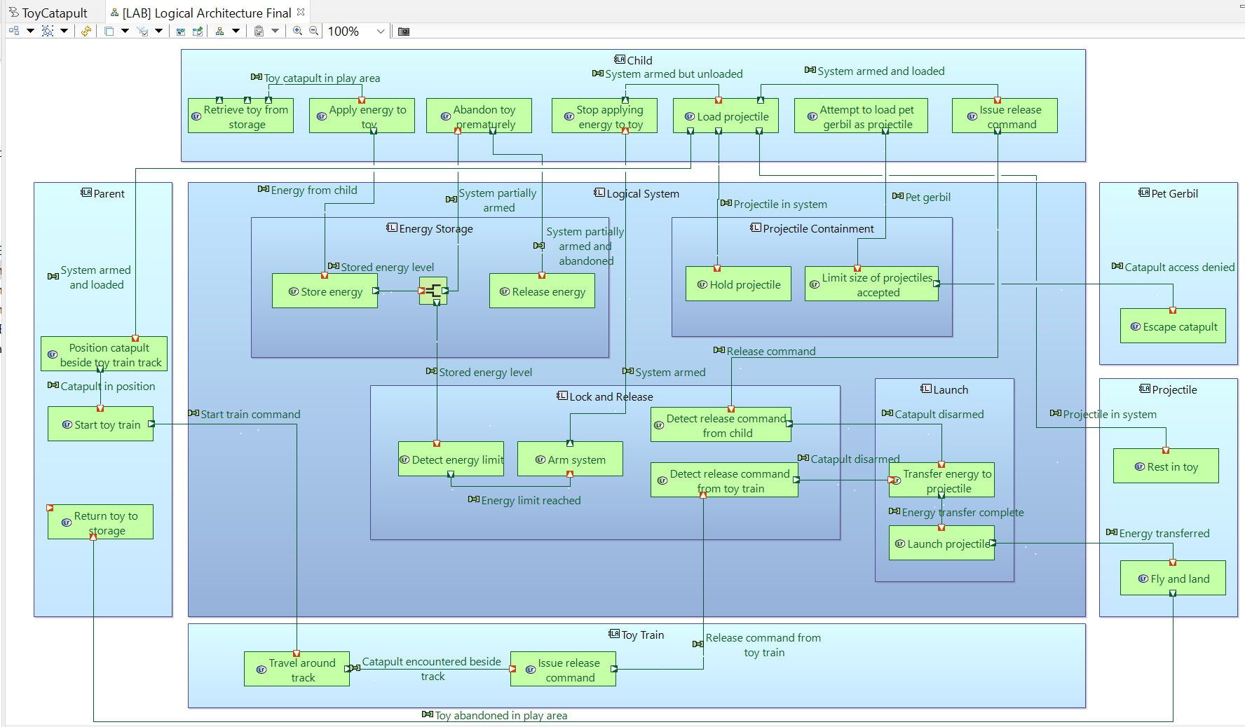
We are now ready to develop the final product of this design phase: a final Logical Architecture diagram to show all functions and interactions
compactly. The techniques to create this diagram are almost identical what was covered in the System Analysis tutorial so we make this
an optional exercise. We just show the final diagram for you to imitate if you so choose.
By cloning the [LAB] Logical Architecture View of Parent Teaches Scenario, adding missing functions and rearranging boxes and ports,
we arrive at a final architecture diagram called [LAB] Logical Architecture Final. Note: you can add or remove functional chains from a diagram using the Functional Chains tool in the palette.
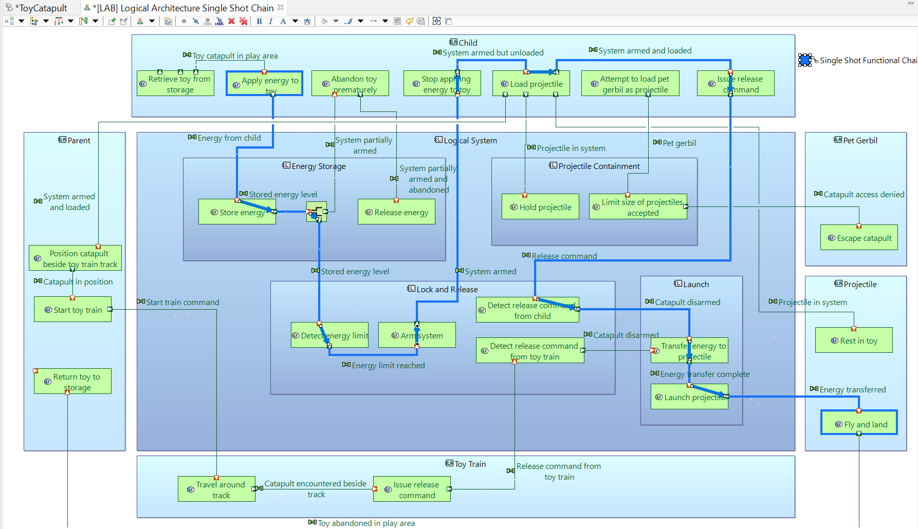
By cloning the [LAB] Logical Architecture Final and adding one of the functional chains, we derive a diagram called
[LAB] Logical Architecture Single Shot Chain.
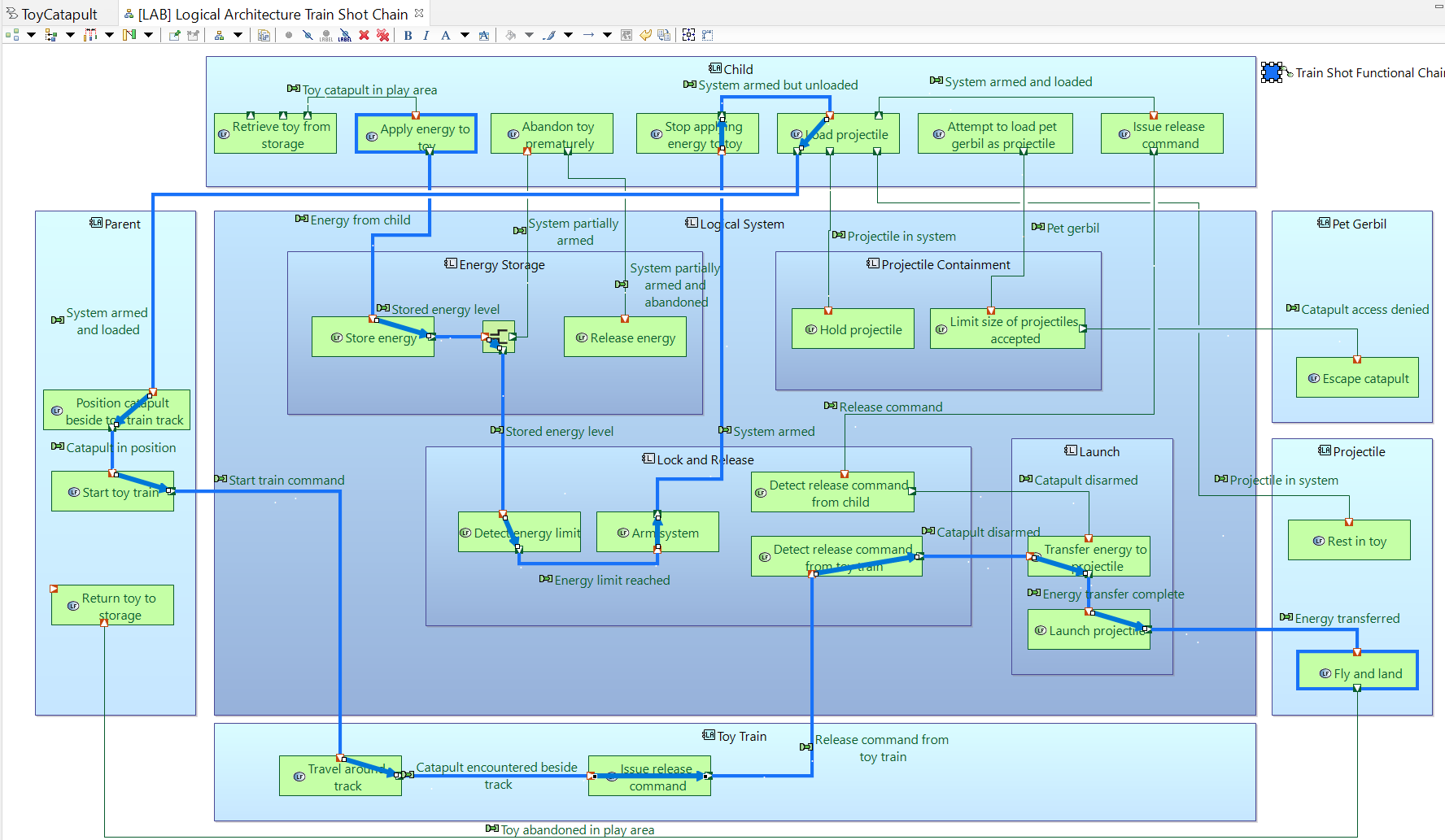
By cloning the [LAB] Logical Architecture Final and adding the remaining functional chain, we derive a diagram called
[LAB] Logical Architecture Train Shot Chain.
This completes the Logical Architecture tutorial.
Back to top
Dällenbach defines a system as follows:
A system is an organized assembly of components. 'Organized' means that there exist special relationships between the components.
The system does something, ie.it exhibits behaviours that are unique to the system.
Each component contributes towards the behaviour of the system and its own behaviour is affected by being in the system.
No component has an independent effect on the system
(a part that has an independent effect and is not affected by the system is an input).
The behaviour of the system is changed if any component is removed or leaves.
Groups of components within the system may by themselves have properties (1), (2) and (3), i.e. they may form subsystems.
The system has an outside –an environment– which provides inputs into the system and receives outputs from the system.
The system has been identified by someone to be of special interest for a given purpose.
Daellenbach, H., McNickle, D., & Dye, S. (2012). Management science: decision-making through systems thinking. Palgrave Macmillan.
 Click Apply in the Actor Transition dialog; and click OK in the pop-up dialog to confirm the action.
The transition will be performed.
Click Apply in the Actor Transition dialog; and click OK in the pop-up dialog to confirm the action.
The transition will be performed.
 You will see that our system actors Child, Parent, Projectile and Toy Train
are realized as logical actors.
You will see that our system actors Child, Parent, Projectile and Toy Train
are realized as logical actors.
 In order to check whether the allocations are also transferred,
(1) select the logical function Escape catapult in the project explorer, and
(2) open the Semantic Browser tab at the bottom window.
(3) You will observe that this function realized the system function with the same name.
(4) You will also notice that the function is already allocated to the logical actor Pet gerbil.
(5) Finally, observe that the functional exchanges have also been transferred from the previous design phase.
In order to check whether the allocations are also transferred,
(1) select the logical function Escape catapult in the project explorer, and
(2) open the Semantic Browser tab at the bottom window.
(3) You will observe that this function realized the system function with the same name.
(4) You will also notice that the function is already allocated to the logical actor Pet gerbil.
(5) Finally, observe that the functional exchanges have also been transferred from the previous design phase.
 Many of these logical functions which realize system functions can be left as they are. But, some will need to be refined.
 Click Apply in the Functional Transition dialog.
The transition will be performed. Confirm by checking the logical function Arm again.
Click Apply in the Functional Transition dialog.
The transition will be performed. Confirm by checking the logical function Arm again.
 This corrects one of the errors in transition: Detect energy limit is now a logical function as well.
 This corrects the remaining error in transition: Transfer energy to projectile is now a logical function as well.
 Click Apply in the capability transition dialog; and click OK in the popup dialog to confirm the transition.
In order to observe that the capabilities are transferred, expand the folder
ToyCatapult.aird → ToyCatapult → Logical Architecture → Capabilities.
Click Apply in the capability transition dialog; and click OK in the popup dialog to confirm the transition.
In order to observe that the capabilities are transferred, expand the folder
ToyCatapult.aird → ToyCatapult → Logical Architecture → Capabilities.
 Save and close the diagram.
 Name the new diagram [LAB] Logical Architecture View of Child Plays Scenario.
Use the Actors and Components tools in the Palette to add the
Child and Projectile actors as well as the Logical System and all its components to the diagram. Re-size the boxes as shown below.
Name the new diagram [LAB] Logical Architecture View of Child Plays Scenario.
Use the Actors and Components tools in the Palette to add the
Child and Projectile actors as well as the Logical System and all its components to the diagram. Re-size the boxes as shown below.

 Continue using the Manage Functional Allocation tool to make the following allocations:


 You may close the diagram now.
 Right-click on the entry for the cloned file, choose Rename and rename it as
[LAB] Logical Architecture View of Parent Teaches Scenario. Then double-click the entry to open the new diagram.
Right-click on the entry for the cloned file, choose Rename and rename it as
[LAB] Logical Architecture View of Parent Teaches Scenario. Then double-click the entry to open the new diagram.
 Use the Allocated Functions tool to add the Detect release command from toy train function to the diagram
in the Lock and Release block. Fix the formats to match the style of the rest of the diagram.
Use the Allocated Functions tool to add the Detect release command from toy train function to the diagram
in the Lock and Release block. Fix the formats to match the style of the rest of the diagram.
 The completed [LAB] Logical Architecture View of Child Plays Scenario looks like this:
 You may close this diagram.
 Activate the [LAB] Logical Architecture View of Child Plays Scenario diagram.
Holding down the Shift or Ctrl key, select all the functional exchanges on the path from Apply energy to toy to Fly and land, including the Split function.
Then, right-click on any of the selected functions and click Functional Chain → Create a Functional Chain.
(If the menu item Functional Chain does not appear, it is likely that you have not selected a complete path of functional exchanges.)
Activate the [LAB] Logical Architecture View of Child Plays Scenario diagram.
Holding down the Shift or Ctrl key, select all the functional exchanges on the path from Apply energy to toy to Fly and land, including the Split function.
Then, right-click on any of the selected functions and click Functional Chain → Create a Functional Chain.
(If the menu item Functional Chain does not appear, it is likely that you have not selected a complete path of functional exchanges.)
 Rename the resulting functional chain as Single Shot Functional Chain.
 You may close this diagram.
 Observe that we could define the states of the entire system, of components, or even of the actors.
In this tutorial, we will define the states for our Logical System. Select the Logical System and click Ok.
Use the suggested name [MSM] Default Region or rename the diagram.
Your diagram with an empty working area will be created.
Observe that we could define the states of the entire system, of components, or even of the actors.
In this tutorial, we will define the states for our Logical System. Select the Logical System and click Ok.
Use the suggested name [MSM] Default Region or rename the diagram.
Your diagram with an empty working area will be created.
 The state transition (also known as a "state change") represented by an arc will be added.
 The transition will be added.
 The Transfer dialog will appear, displaying functions and functional exchanges which are relevant to the Logical System.
This transition happens with the Energy from child exchange.
Double-click to select the functional exchange and click OK.
The Transfer dialog will appear, displaying functions and functional exchanges which are relevant to the Logical System.
This transition happens with the Energy from child exchange.
Double-click to select the functional exchange and click OK.
 The transition arc will be labelled with the name of the functional exchange.
 It is a good practice to check such loops and decide whether we need to take preventive action.
This sequence of state transitions corresponds to a misfire and we conclude that this is not an undesirable behavior.
It is a good practice to check such loops and decide whether we need to take preventive action.
This sequence of state transitions corresponds to a misfire and we conclude that this is not an undesirable behavior.
 Double-click the Store energy function to select and click OK.
Note that you may select multiple functions in the transfer dialog.
Double-click the Store energy function to select and click OK.
Note that you may select multiple functions in the transfer dialog.

 Link it to the Provide safety capability:
 and name it [ES] Child Abandons Toy Prematurely Scenario.
 Using the Components tool, add timelines for the Logical System and the Energy Storage components.
 Put the Logical System timeline on the far right.
 Using the Actors tool, add a timeline for the Child and place it on the left.
 Use the Allocated Function tool to add the following state fragments.
 Use the Functional Exchange tool to add the existing exchange Toy catapult in play area.
 Similarly, add the remaining existing functional exchanges as shown in this diagram:
 Adjust the formatting:

 The completed scenario looks like this: