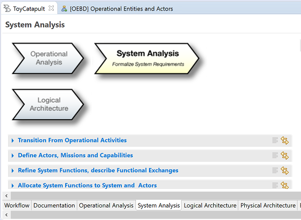
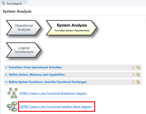
In the System Analysis stage we formalize system requirements.
The explanation in the Workflow window is as follows:
Identify the boundary of the system, consolidate requirements
Define what the system has to accomplish for the users
Model functional dataflows and dynamic behaviour
Note that this is the first time we are using the word system. The operational analysis phase was purposefully conducted in a solution-neutral way.
Now, however, we want to translate operational requirements into system requirements. In this phase, we start thinking of our system,
its boundaries, its interactions with its environment, and what it does. But we still keep the design open because
we will leave the analysis of how it does what it does to the subsequent design phases.
Important note about the design phases in Capella:
A modeling object which is defined in any design phase must be realized in each of the subsequent phases.
For instance, the operational actorChild must be realized as a system actor in the System Analysis phase.
If we do not need this actor at this phase, then it is unnecessary: we should not need it at the operational analysis phase either.
Hence, if we discover that we do not need an object, we must delete it.
On the other hand, we may define new modeling objects as we proceed. They must be realized in all subsequent phases.
Finally, we may realize a modeling object as it is from the previous design phase, without any further modification.
To ease the process of realizing objects from the previous phase (and to prevent re-defining the same objects), Capella supports a quick transition from previous phases.
This will be illustrated in the steps to follow.
Going back to our example project, we were not specific during operational analysis about designing a toy catapult.
Now, to make progress, we focus on a toy catapult as our system of interest.
That is a big jump and we are in fact skipping steps in a design thinking process.
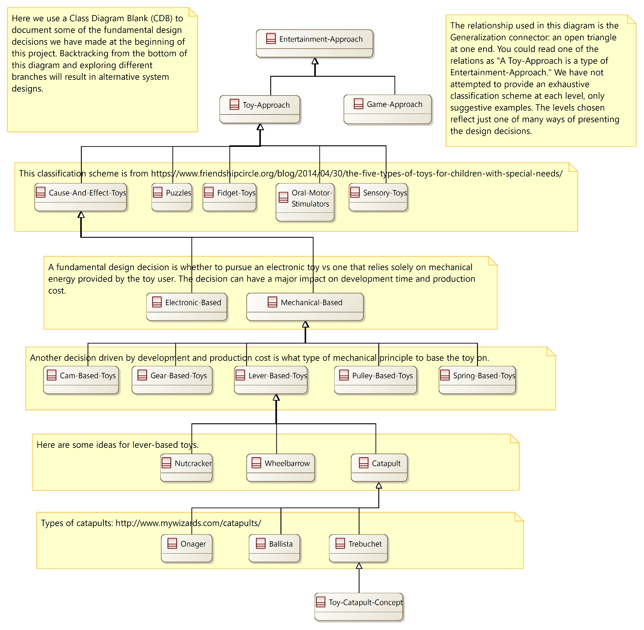
In the chapter on Class Diagram we show how Capella's class diagram feature can be used to model some of these missing steps (context diagrams, architectural trees, and influence diagrams).
For example, we display an architectural tree diagram showing how the toy catapult concept is actually the result of a long sequence of design decisions.
We pick up the design story as
we seek to relate the operational capabilities we identified in the previous chapter to system capabilities.
How will a toy catapult meet the objective of safely entertaining child and parent?
In particular, let us think further about the need to let the parent entertain the child.
We decide that it would be a nice idea if the toy catapult could be triggered by a moving toy, such as a toy train.
This would require the parent to position and start the toy train which would then trigger the toy catapult and initiate a launch.
We can imagine the child's anticipation of this event and see that this would meet the objective of allowing the parent and child
to have fun together.
Our first task will be to realize the operational actors and entities within the systems analysis phase and define the system context.
We illustrate the use of automated transitions in the next chapter (Logical Architecture).
For this chapter we perform the transitions step-wise so that you are familiar with the concept.
Recall that you can open the Workflow diagram by right-clicking ToyCatapult.aird in the
Capella Project Explorer and clicking Open Activity Explorer.
Click the Systems Analysis chevron, or its corresponding tab at the bottom of the panel.
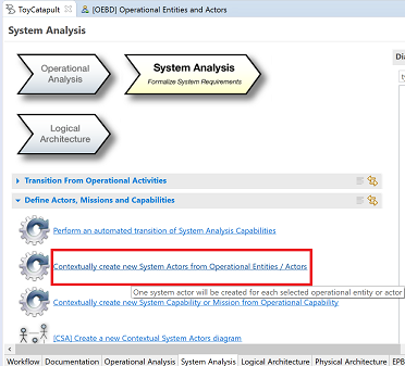
Locate and click the Contextually create new System Actors from Operational Entities/Actors button.
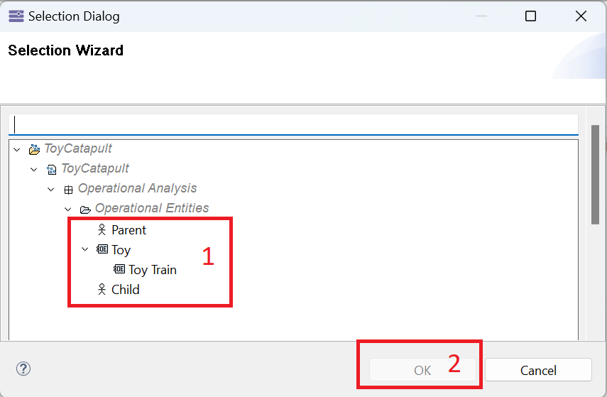
In the resulting dialog, (1) select all of the actors and operational entities, and (2) click OK.
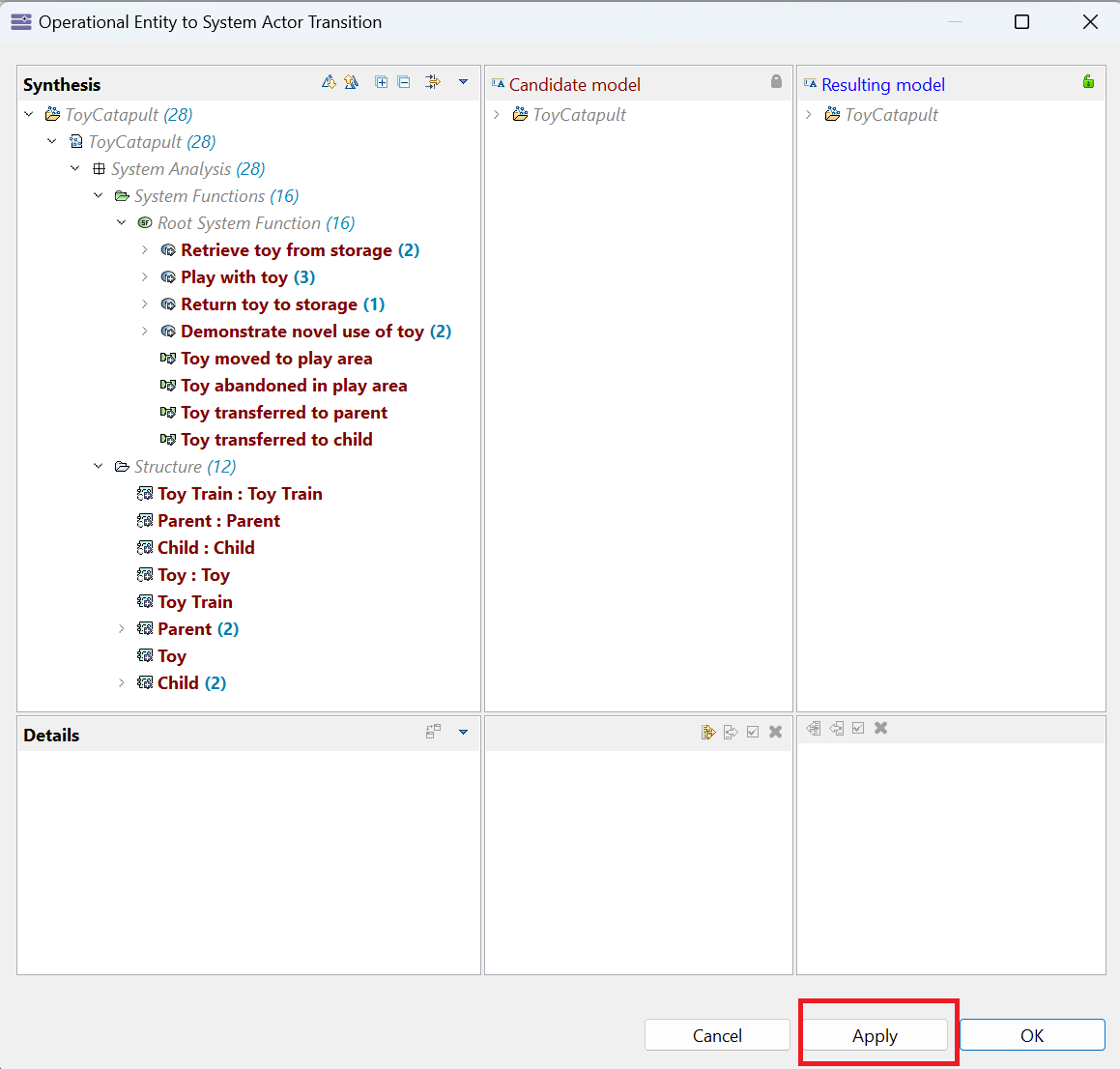
In the next dialog, click the Apply button.
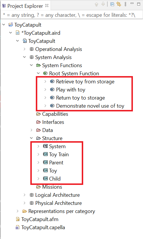
No new diagram is created, but by using the Project Explorer, you can see that the transition has created four system functions
and four system entities/ actors.
Another way to observe the transition results is to use the Semantic Browser.
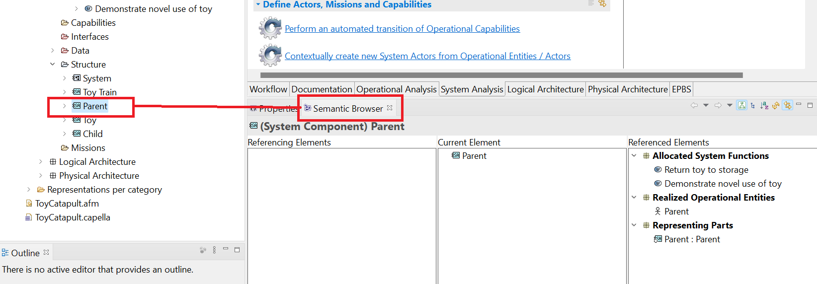
Select the system actor Parent in the Capella Project Explorer and click on the Semantic Browser tab in the bottom window.
The Semantic Browser is composed of three panels. In the center panel, we see the Current Element, which is the Parent actor and any elements it may own.
On the right, we observe Referenced Elements.
Here we see the system functions Demonstrate novel use of toy and Return toy to storage
which have been created automatically (based on their counterparts in Operational Analysis).
We also see that they have been
allocated automatically to the Parent actor. We also see a link back to the Operational ActorParent
which gave rise to the System Actor.
Finally, on the left, we observe Referencing Elements.
This panel will show diagrams and elements which reference the Parent actor.
There are no such diagrams or elements yet.
Note that the semantic browser can be used for any object, and it allows us to navigate quickly to objects related to
the focused object.
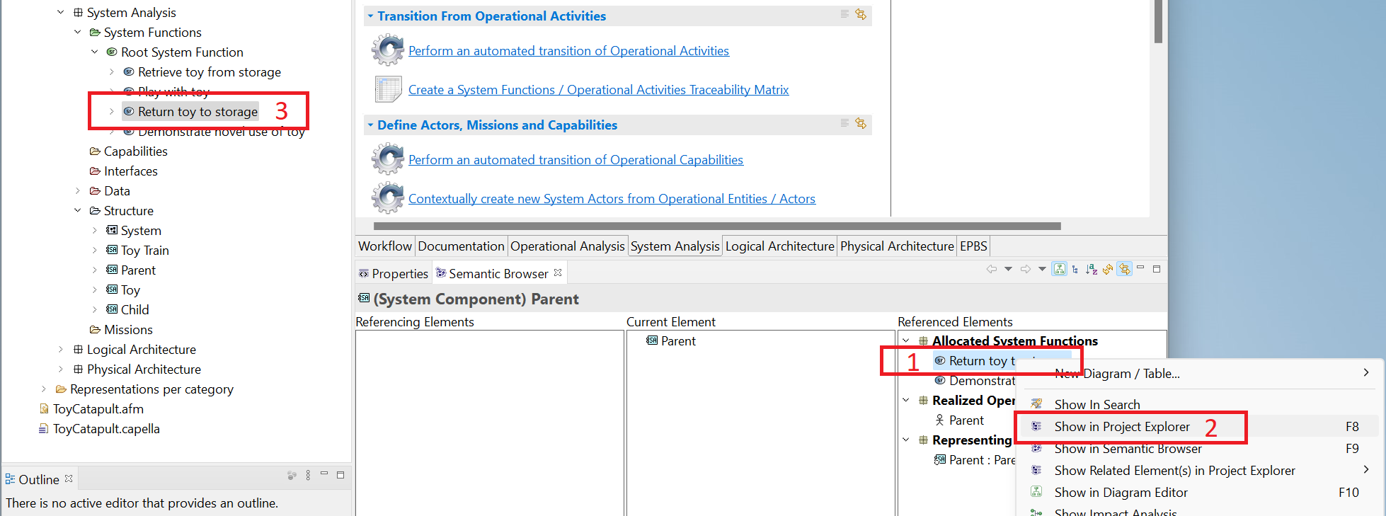
If you right-click any object in the semantic browser, you will see options such as
Select in Project Explorer and Show in Semantic Browser.
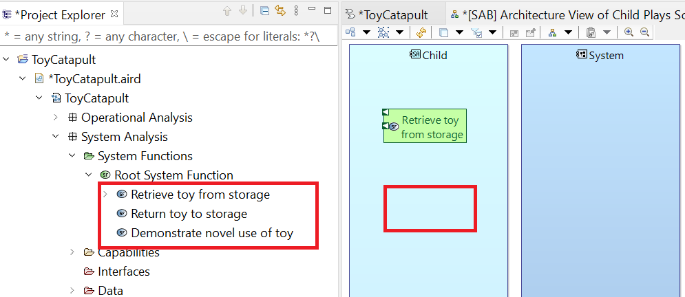
For example, to see the location of the system function Return toy to storage created by the transition,
(1) right-click on Return toy to storage under Allocated System Functions on the right and
(2) click Select in Project Explorer.
This process will locate the object in the explorer for you (3).
As might be expected, it is located in the
ToyCatapult.aird → ToyCatapult → System Analysis → System Functions folder.
The Semantic Browser is a powerful feature of Capella and becomes more useful as your model gets larger and more complex.
We suggest you keep the Semantic Browser tab selected in the bottom panel,
and observe the information provided in the left, middle and right panels as you select different objects while working on diagrams.
Having transitioned our operational actors to the system analysis phase, we can now create our system context.
Click [CSA] Create a new Contextual System Actors diagram in the
System Analysis tab of the Workflow.
Rename as [CSA] System Context and click OK.
Your diagram will be created and opened.
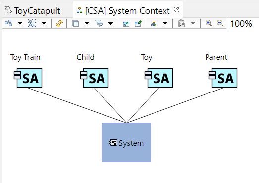
Firstly, we observe that the System element has been added automatically, as it is the focus of this design phase.
We sometimes use the phrase system of interest to distinguish this focal system from other systems which may be mentioned.
In our mind, the system of interest is the toy catapult we are developing.
Secondly, all of the system actors have been added to the diagram and connected to the system of interest.
Note that the Toy system actor is a generic placeholder for other toys which may interact with our toy catapult.
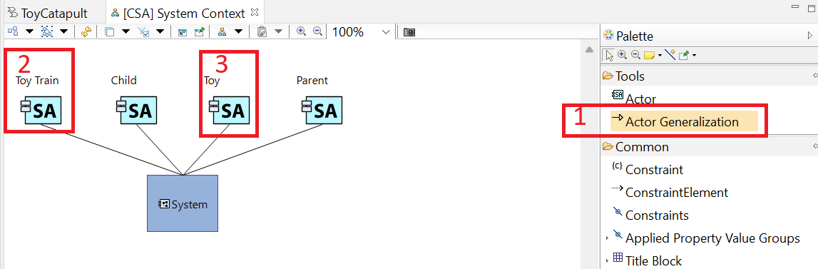
The Toy train is a specific example of a toy we will make explicit use of. We can convey that concept as follows.
(1) Click on the Actor Generalization tool in the Palette,
(2) click on the Toy train actor in the diagram, and
(3) click on the Toy actor in the diagram.
This adds an arrow to the diagram with an open triangle at one end. (We have moved the actor Toy to be closer to the Toy Train.) We read this relationship as "the Toy
is a generalization of the Toy train actor," or, alternatively, "the Toy train
is a specific example of the Toy type of actor."
The toy catapult is designed to throw projectiles. So a fundamental design decision is whether the projectiles are part of the system
or external to the system. Phrased another way, are projectiles inside the system boundary or outside? Such questions are fundamental to
systems architecture. Ignoring these decisions can lead to serious problems later in development. It is best to make such decisions clear as part of
the architecture design. In the case of the toy catapult, we imagine that we could include the design of projectiles as part of the system design.
For example, we might choose to provide styrofoam balls as part of our toy. On the other hand, the child is unlikely to restrict his or her projectile choice to
the projectiles we provide. Our design decision is therefore to exclude projectiles from the system. But they are essential to describing the behavior
of the system so we need to add projectiles as external "actors," similar to the treatment of the Toy train.
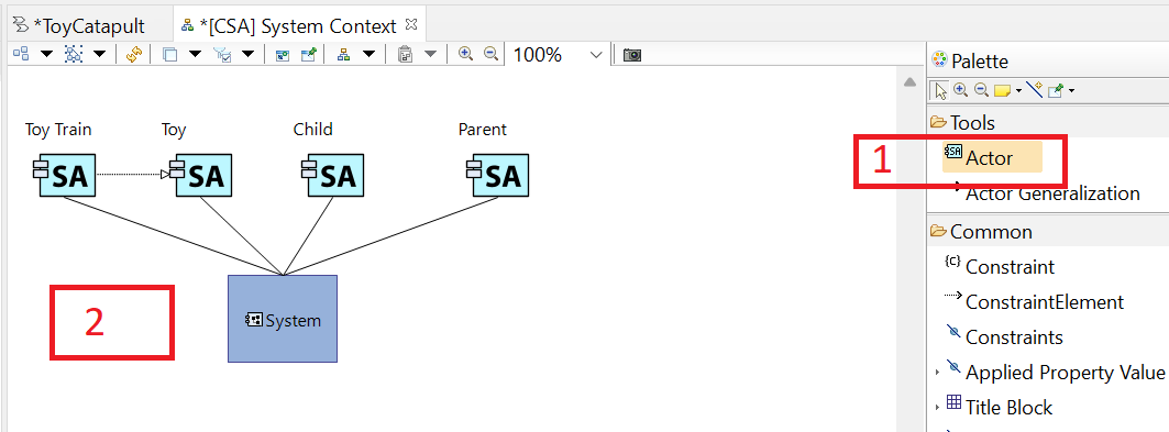
Make sure the [CSA] System Context diagram is still active. (1) Click on the Actor button in the Palette
and (2) click in an open area of the diagram.
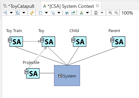
Rename the new actor as Projectile and add an Actor Generalization arrow from
the Projectile actor to the Toy actor as described in an earlier step. (The Projectile is a type of Toy.)
This completes our System Context diagram. After saving, you may close the tab by clicking the x icon.
Similar to the actors, we need to transition operational capabilities to the system phase.
(1) Click [CSA] Contextually create new System Capability or Mission from Operational Capability in the
System Analysis tab of the Workflow and (2) select the System Mission option.
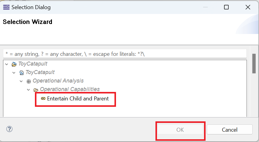
In the next dialog, select Entertain child and parent and click OK.
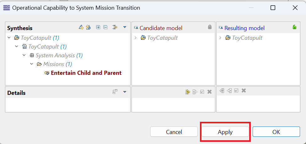
In the dialog shown below, simply click the Apply button.
Using the Project Explorer, locate the newly added mission Entertain Child and Parent.
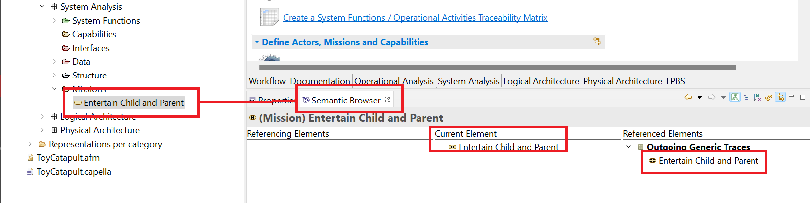
Using the Semantic Browser, observe that this mission traces back to the Entertain Child and Parent
operational capability (OC).
Double-click on the mission Entertain Child and Parent and type the following statement into the Summary section:
Amuse a 4-year-old child safely creating an opportunity for parent and child to play together in a way that delights them both. Click the Finish button.
In this way, we have captured our aspirational mission statement as part of the system documentation.
Next, we will detail this mission and define the actor involvements.
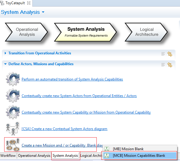
Click Create a new Mission and / or Capability Blank diagram in the System Analysis tab of the workflow.
Click [MB] Mission Blank in the pop-up options.
Rename the diagram or save it as suggested ([MB] Missions).
Your diagram will be opened with an empty workspace.
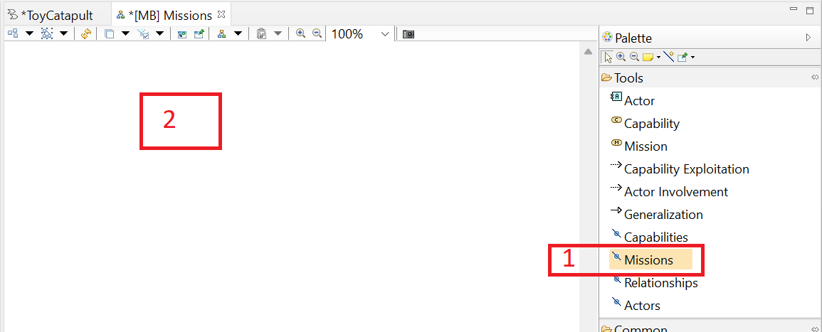
(1) Click on the Missions tool in the Palette, and
(2) click anywhere in the working area.
Recall that the icon is used to insert existing modeling objects,
and we already created our system mission.
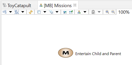
Select the system mission Entertain Child and Parent in the transfer dialog (not shown) and click OK.
The mission will be added to the diagram.
This mission is related to two of our actors: child and parent.
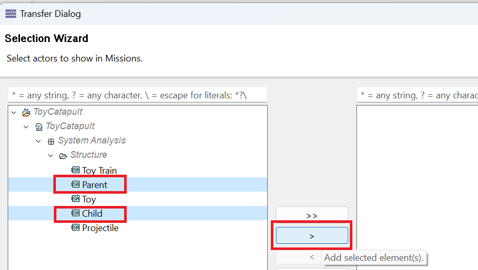
Click the Actors tool in the Palette,
click anywhere on the diagram,
select Child and Parent in the transfer dialog, click the > button and click OK to add them to the diagram.
Move the actors to appropriate locations by dragging and dropping.
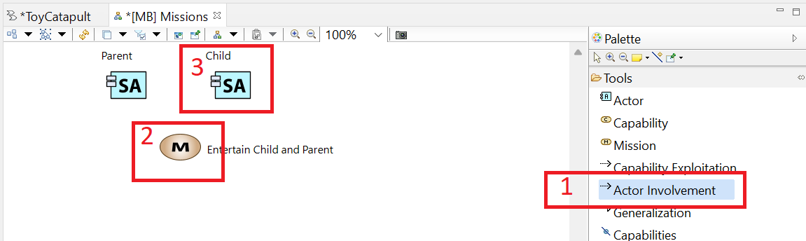
(1) Click on the Actor Involvement tool in the Palette,
(2) click on the mission Entertain Child and Parent, and
(3) click on the Child actor, to define the actor involvement.
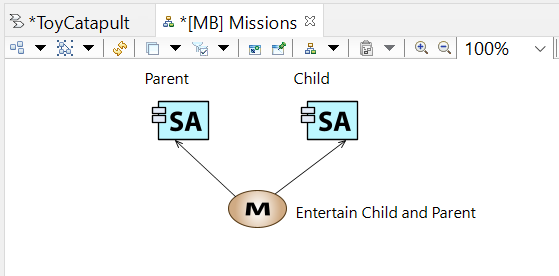
Repeat the process for the Parent.
After you complete this, the mission diagram should look like the image below:
Close the diagram.
In complex projects, it is a good practice to divide the mission into components, called capabilities.
Though this is a simple project, we will illustrate the process by defining three capabilities which arise from our mission.
Click Create a new Mission and / or Capability Blank diagram in the System Analysis tab of the workflow.
Click [MCB] Mission Capabilities Blank in the pop-up options.
Rename the diagram or save it as suggested ([MCB] Capabilities).
Your diagram will be opened with an empty workspace.
Add our existing system mission to the diagram by
(1) clicking the Missions tool in the Palette,
(2) clicking anywhere in the diagram,
(3) selecting the existing mission Entertain CHild and Parent in the transfer dialog and clicking OK (as in the previous step).
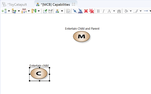
We will now define three new capabilities.
In order to define our first capability,
(1) click the Capability tool in the Palette, and
(2) click anywhere in the working area.
Rename the capability, Capability 1, as Entertain child.
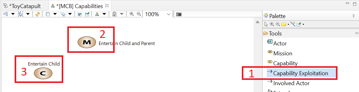
Next, we will define the relation between our mission and the new capability.
(1) Click the Capability Exploitation tool in the Palette,
(2) click our mission on the diagram, and
(3) click on the new capability.
The newly-defined capability exploitation will be represented by an arc.
We read this relation as "The mission 'Entertain Child and Parent' exploits the system capability 'Entertain Child.'"
Repeat the process to define two more capabilities (and exploitations):
Engage parent
Provide safety
When finished, the diagram should look like the following diagram:
Note from the [MCB] Capabilities palette, we could add actors to the diagram (using the Actors tool) and define
involvement between actors and capabilities (using the Involved Actor tool).
This provides flexibility in relating different capabilities to different actors.
We will not utilize this feature in this project, but it can be useful in more complex projects.
We have finalized defining our mission, capabilities, and actor involvments.
Now, we are ready to refine our scenarios.
We will use the same approach for developing scenarios as we did during Operational Analysis.
That is, we will use Architecture Blank diagrams with swimlanes to define the system functions and functional exchanges.
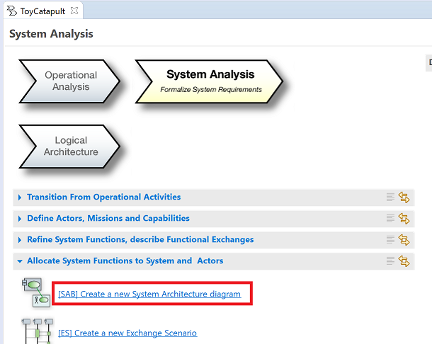
Create a system architecture diagram by clicking [SAB] Create a new System Architecture diagram
in the System Analysis tab of the workflow window.
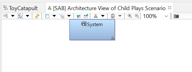
Rename the diagram [SAB] Architecture View of Child Plays Scenario.
You will see the System actor already located on the diagram.
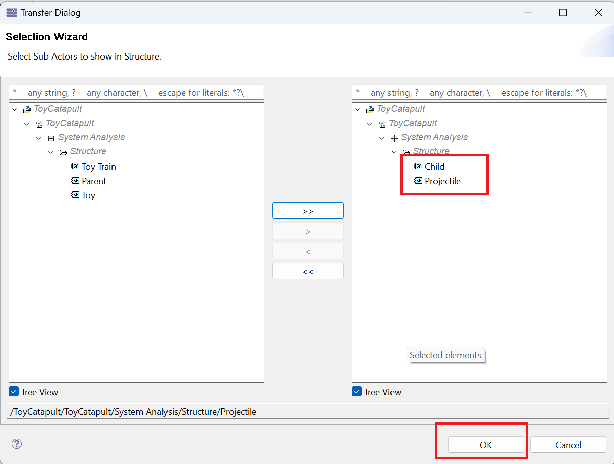
Click on the Actors tool on the Palette and click anywhere in the diagram.
In the resulting Transfer Dialog select just the Child and Projectile actors and
transfer them to the diagram.
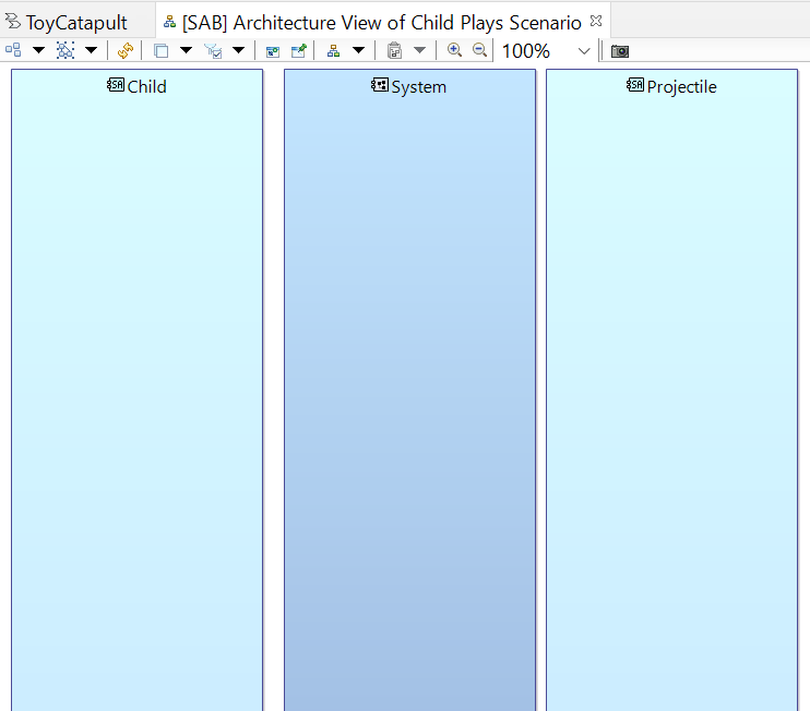
Rearrange and resize the blocks on the diagram to look like this:
That is, our user, the Child actor, is placed to the left of the System, the external entity, the Projectile actor, is placed to the right,
and the boxes are stretched in height to form visual swimlanes.
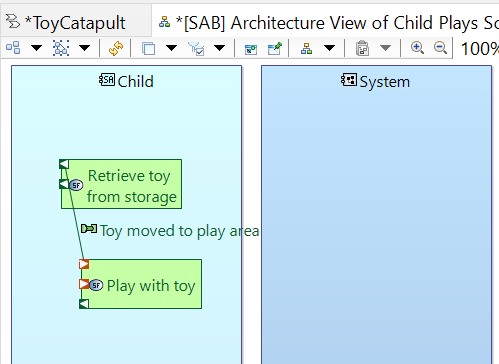
Click on the Allocated Functions tool on the Palette and click anywhere in the Child block.
Transfer all functions to the diagram using the >> button. Move and resize the functions as shown.
Recall that these activities were transitioned into system functions from the previous design phase.
The system functions were created during the transition of the operational actors to system actors.
Recall that each operational activity is allocated to a single operational actor.
When we transition operational actors, system functions corresponding to the allocated activities are also created.
Now that we have a specific system in mind (a toy catapult) we can develop a more detailed description of what was the "Child plays with toy" activity.
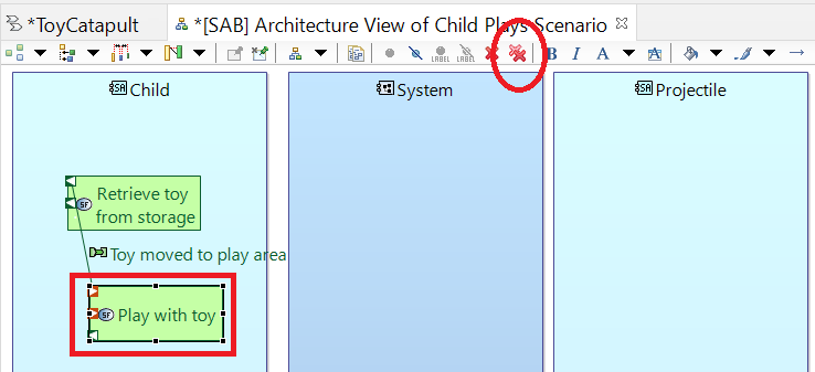
We will begin by deleting the Play with toy system function as we will be replacing it with more detailed functions.
Right-click on the Play with toy function and navigate the menu to the
Edit → Delete from Model command.
Note that there are two shortcuts to the Delete from Model command. One is to use the keyboard command CTRL+D and the other is to
click the double-X button on the menu bar:
Confirm the deletion by clicking "Yes" in the resulting dialog. Note that the function Play with toy has not only disappeared from
the diagram but it has also disappeared from the list of system functions in the Project Explorer.
The interaction Toy moved to play area has also been deleted from the model.
When describing system functional requirements, we do our best to think abstractly. If we are too specific in our requirements, we deny the design
team room to creatively meet our true requirements. In system analysis it is not our job to indicate how the system will perform its tasks.
It is our job simply to identify what those tasks (i.e. functional requirements) are. A clear list of functional requirements can be
enormously helpful to the design team.
We think through the use case of a child playing with a toy catapult and we perceive three main activities: arming the toy, loading the toy with a projectile, and launching the projectile.
Let's break those activities down into functions.
Using the System Function tool in the Palette, add functions Apply energy to toy and Stop applying energy to toy
to the Child actor block. Similarly, add functions Store energy, Detect energy limit, and Arm system to
the System actor block.
Observe that we have not specified how energy is to be stored or what mechanism will be used to arm the system. Those design decisions are
deferred until a deeper level of analysis. But you see basic functional requirements of the system emerging from this analysis.
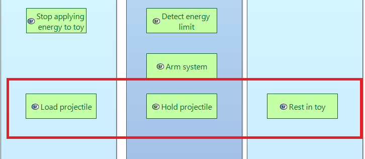
It is a little awkward to treat the projectile as an actor since it is so passive. Nevertheless, we will show its participation in the scenario by assigning it some functions.
Using the System Function tool in the Palette, add the function Load projectile
to the Child actor block. Add the function Hold projectile to the System actor block.
Finally, add the function Rest in toy to the Projectile actor block.
Extend the height of the actor blocks as needed to accommodate the new functions.
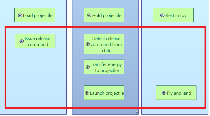
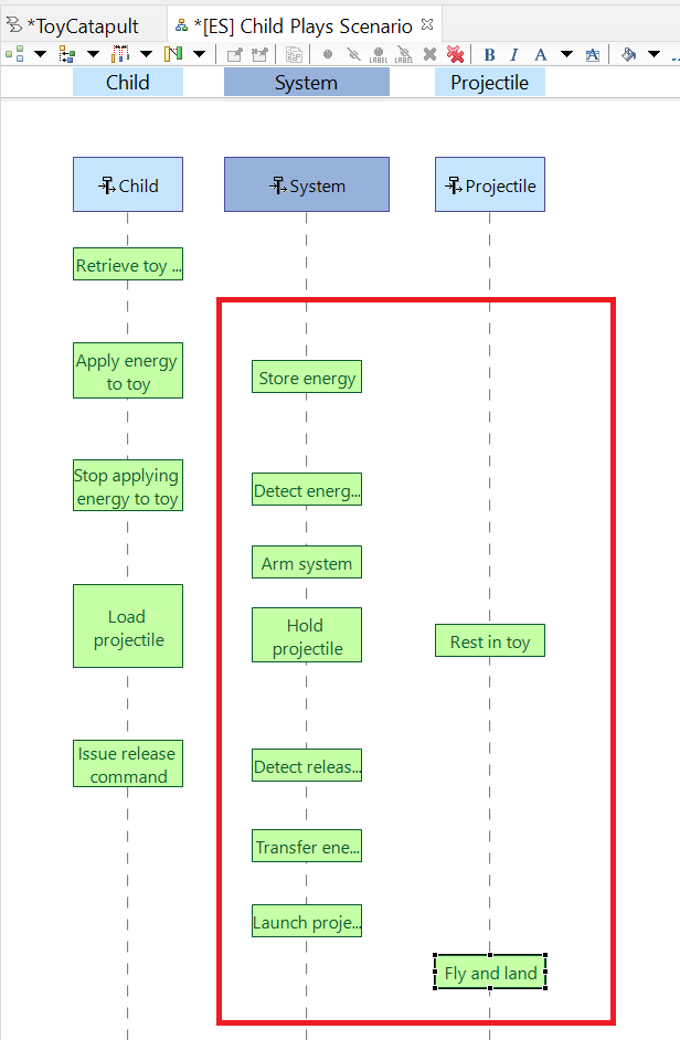
Using the System Function tool in the Palette, add the function Issue release command
to the Child actor block. Add the functions Detect release command from child,
Transfer energy to projectile, and Launch projectile to the System actor block.
Finally, add the function Fly and land to the Projectile actor block.
Extend the height of the actor blocks as needed to accommodate the new functions.
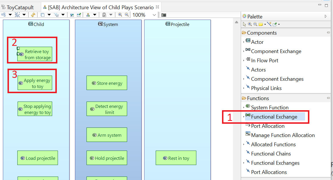
As we did in Operational Analysis, we now proceed to identify interactions between these system functions. The proper name for an interaction in this phase is Functional Exchange.
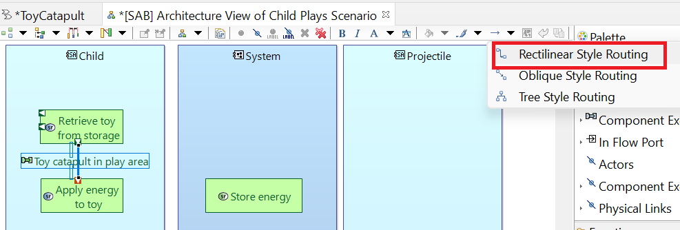
(1) Click the Functional exchange tool in the palette, then (2) click on the activity Retrieve toy from storage, and (3) click on the activity Apply energy to toy.
Name the resulting functional exchange Toy catapult in play area. Choose the line style Rectilinear Style Routing.
Repeat the previous step, creating functional exchanges for each of the rows in the following table:
From Function
To Function
Functional Exchange Name
Apply energy to toy
Store energy
Energy from child
Store energy
Detect energy limit
Stored energy level
Detect energy limit
Arm system
Energy limit reached
Arm system
Stop applying energy
System armed
Stop applying energy
Load projectile
System armed but unloaded
Load projectile
Rest in toy
Projectile in system
Load projectile
Hold projectile
Projectile in system
Load projectile
Issue command to release
System armed and loaded
Issue command to release
Detect command to release from child
Release command
Detect command to release from child
Transfer energy to projectile
Catapult disarmed
Transfer energy to projectile
Launch projectile
Energy transfer complete
Launch projectile
Fly and land
Energy transferred
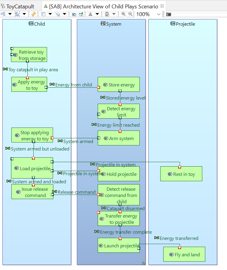
After adding these functional exchanges (and prettifying the layout) you will have something like this:
Next, we will clone this diagram and modify it to describe the scenario Parent teaches child.
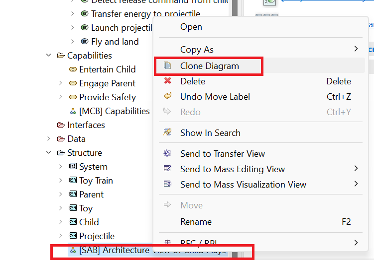
Close the current diagram ([SAB] Architecture View of Child Plays Scenario) so that we do not accidentally make changes to it.
Instead, right-click on its entry in the Project Explorer and choose Clone Diagram.
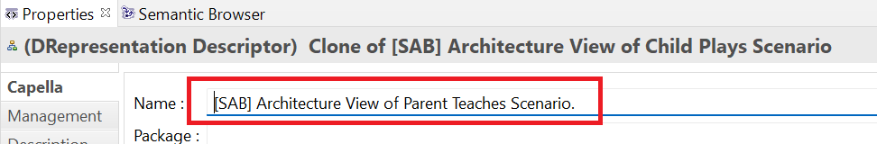
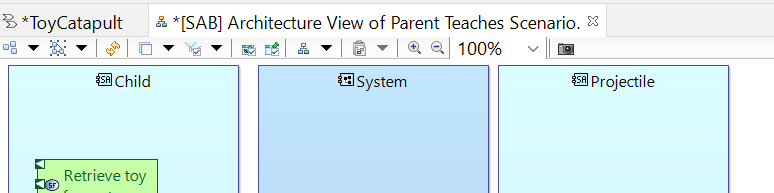
Rename the new diagram as [SAB] Architecture View of Parent Teaches Scenario.
Double-click on the entry for this diagram to open the diagram for editing.
Click the Actors tool in the Palette and click in any open space of the diagram.
In the resulting selection dialog, (1) select just the Parent and Toy train actors,
(2) click the > button, and click OK.
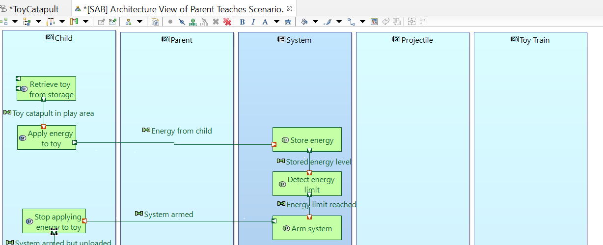
Reposition the Parent block between the Child and the System blocks
and the Toy train block on the far right. Resize the blocks for symmetry.
Note our convention that we place users to the left of the System and supporting entities to the right.
Extend the height of each actor block. Then select the functions at the bottom and move them downward to create more space
in the diagram in which to insert the Parent and Toy train functions.
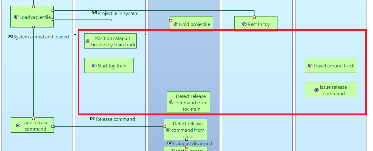
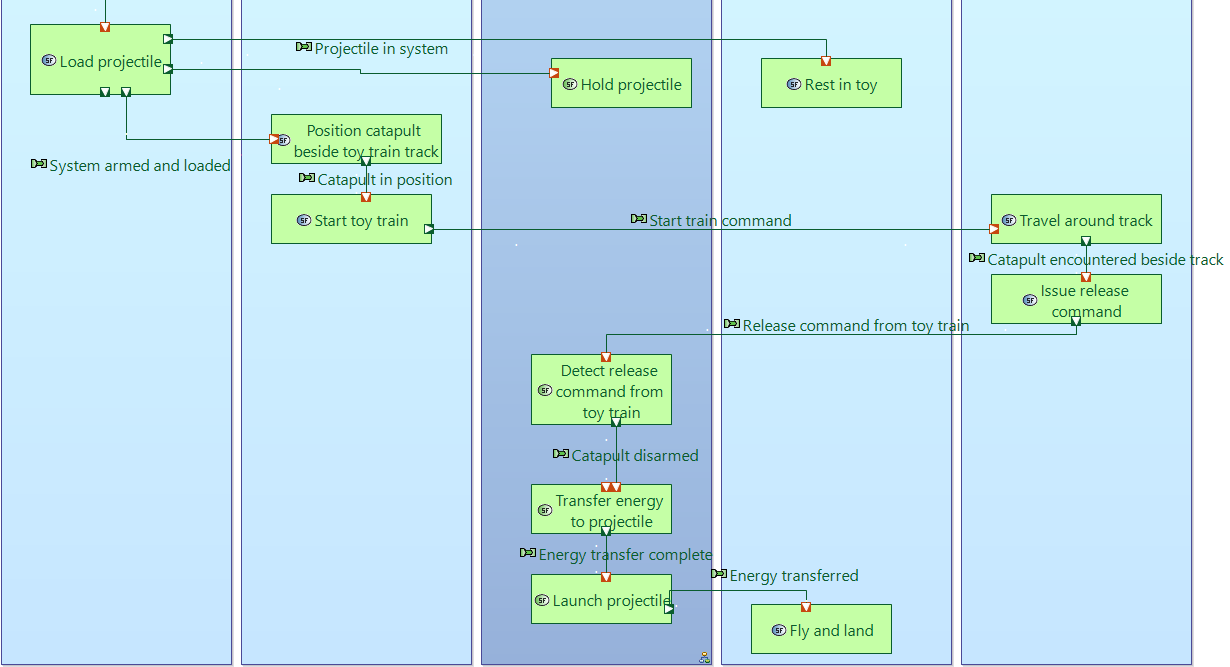
Using the System Function tool on the Palette, add the following system functions:
Position catapult beside toy train track and Start toy train to the Parent actor;
Travel around track and Issue release command to the Toy train actor; and
Detect release command from toy train to the System actor.
Note that we have made an interesting discovery by thinking through these scenarios.
To support the two scenarios, the system must be capable of two similar functions: Detect release command from child
and Detect release command from toy train.
This poses a design challenge: the child will likely find it easiest to trigger the catapult release with some downward vertical movement.
But for the passing toy train to trigger the release, we would likely want to use a lateral trigger movement. So, our toy catapult will require
a novel trigger mechanism that can work both vertically and horizontally. Again, in the system analysis phase, our job is to capture these system functional
requirements, not to decide how to satisfy them. The main point is that you can expect lots of such discoveries as you perform detailed
scenario analysis.
?????.
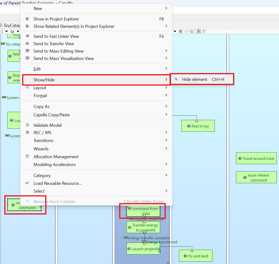
Holding the shift key down, select both the Detect release command from child and the Issue release command (Child version) activities.
Then right-click the selection and choose Hide/Show → Hide element. They are not relevant activities in this scenario.
Using the Functional Exchange tool in the Palette, create functional exchanges for each of the rows in the following table:
From Function
To Function
Functional Exchange Name
Load projectile
Position catapult beside toy train track
System armed and loaded
Position catapult beside toy train track
Start toy train
Catapult in position
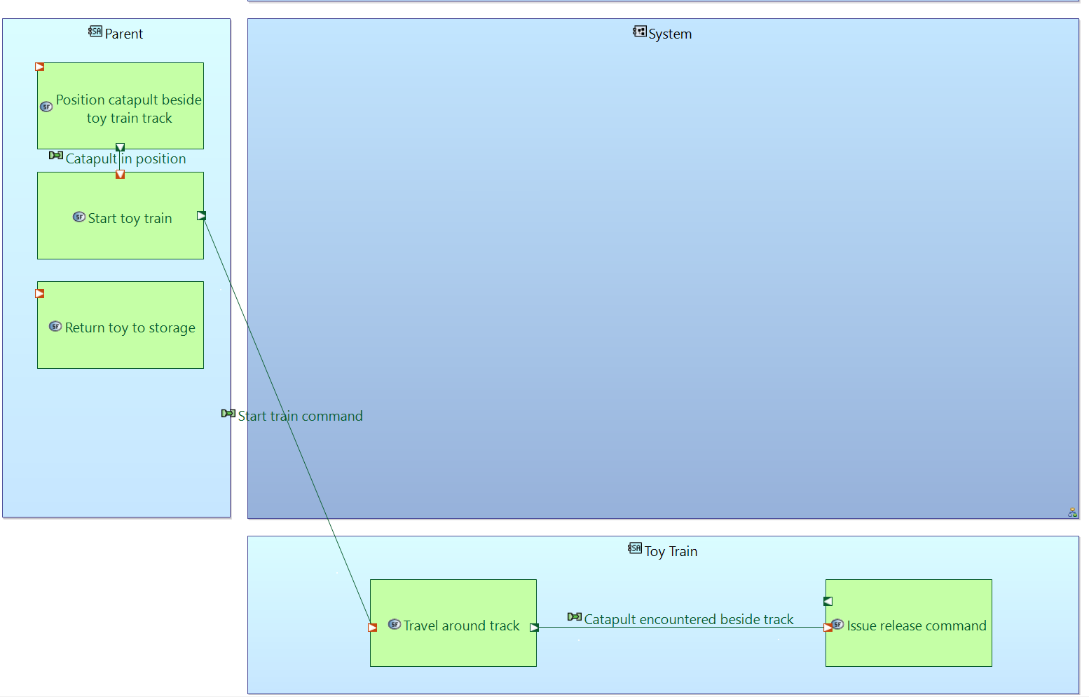
Start toy train
Travel around track
Start train command
Travel around track
Issue release command
Catapult encountered beside track
Issue release command
Detect release command from toy train
Release command from toy train
Detect release command from toy train
Transfer energy to projectile
Catapult disarmed
When completed your diagram should look like this:
This completes an architectural description of the Parent teaches scenario. We have one more scenario to describe. We will use that
scenario to explain what we mean by the Provide safety capability. The problem with this capability is that safety is a system
quality. It is not easily measured. But, here again, we can use scenarios to describe what we mean by "safety."
We imagine ways in which the system can fail to be safe and then develop system requirements to prevent those situations or limit their damage.
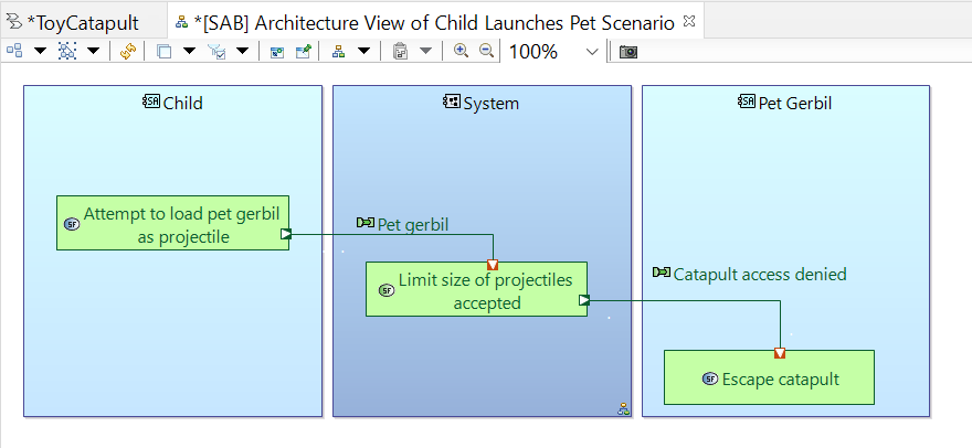
As a simple example, we examine one way in which the system could fail to be safe. If the child were to attempt to launch
the pet gerbil as a projectile, this would cause harm to the pet. A system requirement to mitigate this
risk might be to "Limit the size of projectiles accepted." In that way, projectiles and pets beyond a certain size could not be placed in the catapult. As with other
system requirements, it is not our job in this phase to decide how to meet the requirement. It is sufficient to capture the requirement.
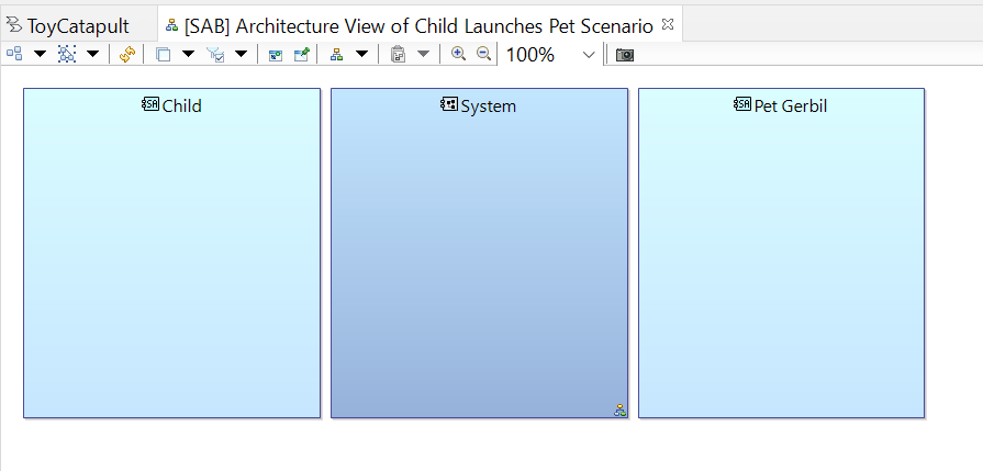
Create a new System Architecture diagram and name it [SAB} Architecture View of Child Launches Pet Scenario.
Use the Actors tool in the Project Explorer to add the Child actor.
Use the Actor tool to create a new actor, the Pet gerbil. Size and position the actor blocks as follows:
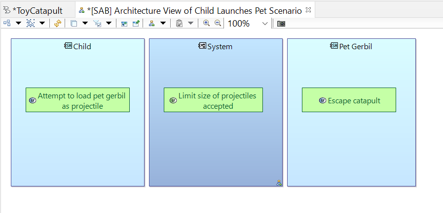
Use the System Function tool to create functions as follows:
Attempt to load pet gerbil as projectile allocated to the Child actor;
Limit size of projectiles accepted allocated to the System actor; and
Escape catapult allocated to the Pet gerbil actor;
Use the Functional Exchange tool to create the following exchanges.
As mentioned in the chapter on Operational Analysis, an architecture diagram with swimlanes is only suggestive of activity sequences. A scenario diagram is more explicit.
Furthermore, a scenario diagram is explicitly linked to a capability thus documenting how that capability is fulfilled by the system.
In this section, we will create a scenario diagram for each of our three scenarios (Child Plays, Parent Teaches, and Child Launches Pet).
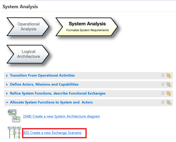
No new activities or functional exchanges will be added so this is largely a mechanical exercise.
Create an exchange scenario diagram by clicking [SAB] Create a new Exchange Scenario
in the System Analysis tab of the workflow window.
In the resulting dialog, select the Entertain child system capability and click OK.
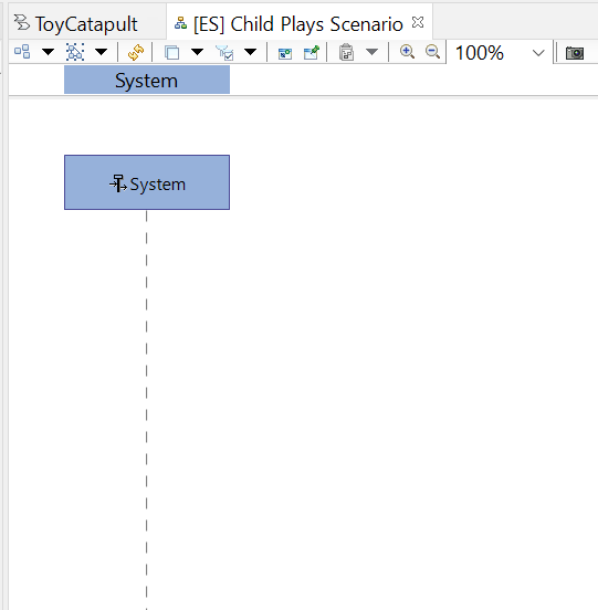
In the following dialog, name the diagram Child Plays Scenario. The diagram should appear pre-loaded with a timeline
for the System.
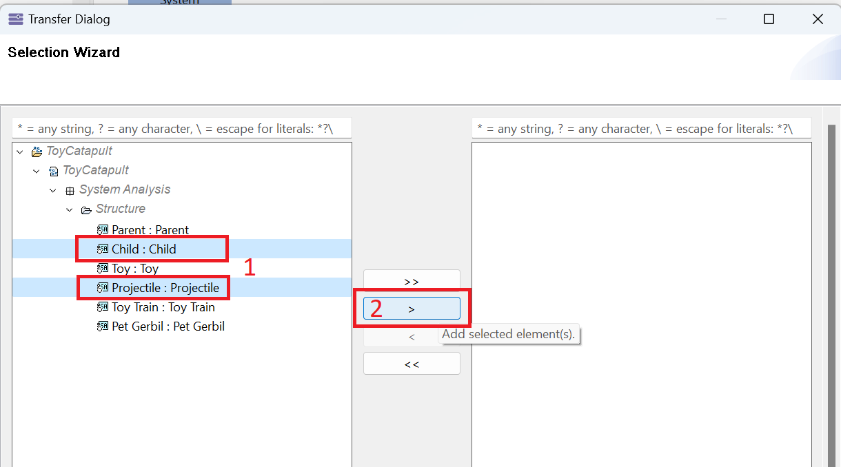
Next we add timelines for the Child and Projectile actors. Click the Actors
tool in the Palette and click anywhere in the diagram. Then (1) select just the Child and Projectile
actors, (2) click the > button, and click OK.
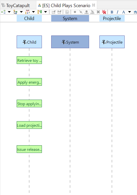
Our convention in these sequence diagrams is to put the user timeline to the left of the system timeline and to put all other supporting actors to the right.
Rearrange the timelines according to this convention:
Using the Allocated Function tool in the Palette, click on the Child timeline and, one by one,
add all of the Child system functions. They will be added as State Fragments
as explained in the Operational Analysis tutorial.
Similarly add all of the System and Projectile system functions.
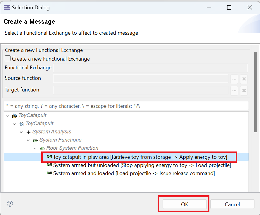
(1) Click the Functional Exchange tool in the Palette,
(2) click on the Child timeline between the Retrieve toy from storage state fragment and the
Apply energy to toy state fragment, and (3) click a second time in the same area.
In the resulting Create a Message dialog, select the existing functional exchange Toy catapult in play area and click OK.
Resize the vertical box created on the timeline so that it spans the Apply energy to toy state fragment.
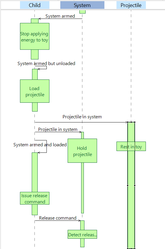
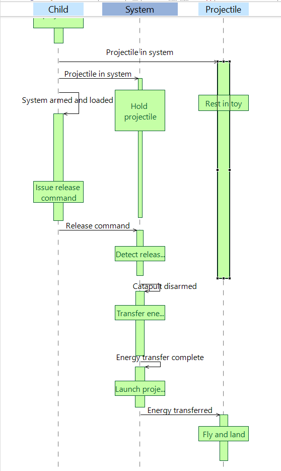
Repeat the previous step, creating messages for each of the functional exchanges in Child Plays scenario.
Use the draggable viewport in the Outline panel to view different portions of your diagram. (We showed how to add this panel in the
Getting Started Tutorial.
The next images show the resulting Child Plays Scenario diagram.
This completes our description of the Child Plays Scenario diagram. We have two more scenarios to describe.
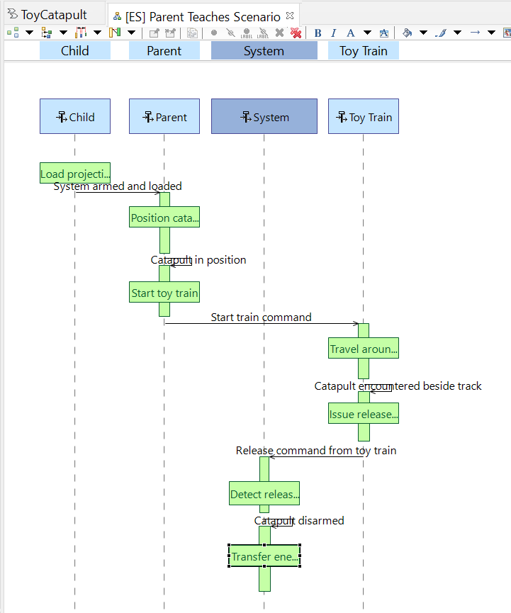
Repeat the process to create the Parent Teaches Scenario diagram (attached to the Engage Parent capability) and populate it with the following subset of state fragments and messages.
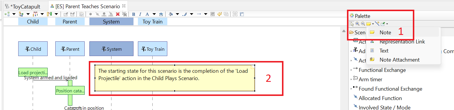
To assist the reader in understanding this scenario, we add a note by (1) clicking the Create a Note button
in the Palette, and (2) clicking near the top of the diagram. Enter the text,
"The starting state for this scenario is the completion of the 'Load Projectile' action in the Child Plays Scenario."
This note has no role in the model. It is a graphical addition to the diagram to help its readability. Add another note at
the bottom of the diagram reading "The ending state for this scenario is initiation of the 'Transfer energy to projectile' action in the Child Plays Scenario."
Repeat the process to create the Child Launches Pet Scenario diagram (attached to the Provide Safety capability) and populate as follows.
This completes our scenario descriptions for the System Analysis phase.
We can use functional chains (similar to the Operational Process groupings in the operational analysis stage) to define certain use case scenarios of the system.
Recall that we started our project with two scenarios Child Plays and Parent Teaches.
From these scenarios, we can define two functional chains: Single Shot and Train Shot. We will ignore the other scenario, Child Launches Pet..
Locate and click the Create a new Functional Dataflow Blank Diagram button
on the System Analysis tab of the Activity Explorer.
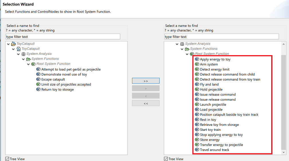
Name the diagram [SDFB] Root System Function - Chains. Then use the Functions tool to add all
functions to the diagram except the following:
Attempt to load pet gerbil as projectile
Demonstrate novel use of toy
Escape catapult
Limit size of projectiles accepted
Return toy to storage
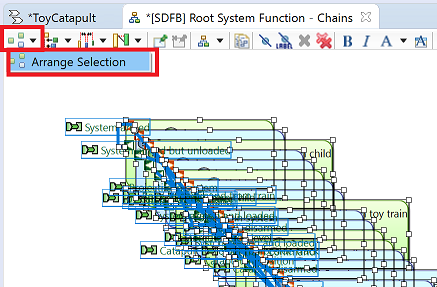
The result is a mess: all of the functions have been added on top of each other.
While all of the functions are still selected, as a group, click the Arrange Selection menu item.
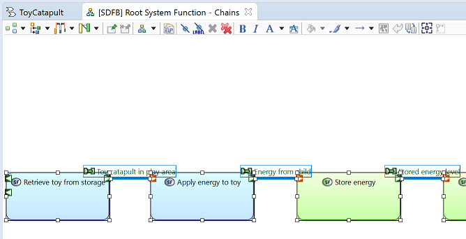
The result is a more logical layout of the functions.
The diagram layout is quite large.
Note that the Palette includes tools to zoom in and out of diagrams.
If your mouse has a wheel, then Ctrl+Wheel can be used to zoom in and out as well.
The draggable viewport in the Outline window is also useful for panning around the view.
Note also that you can select groups of functions (and their connecting exchanges) by dragging a rubber-band box around the group.
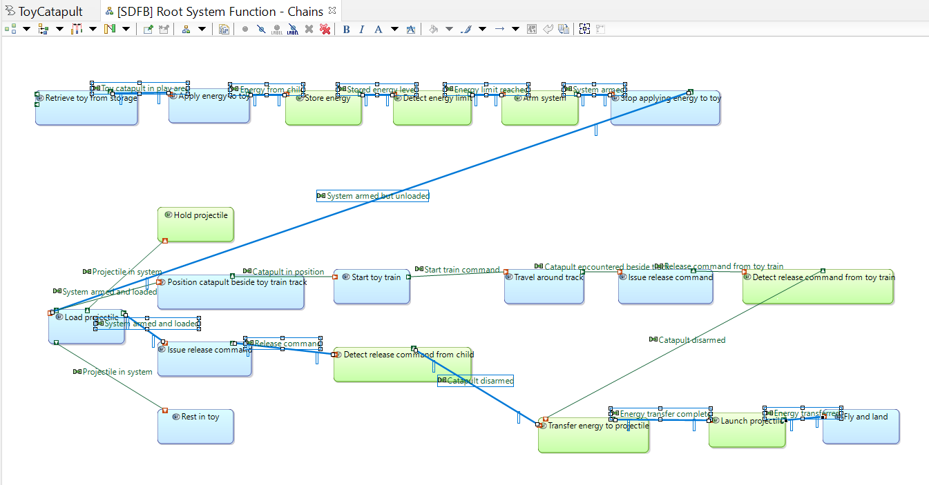
Use zooming, selection, and dragging to create a more compact view of the functions.
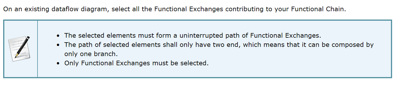
The rules for defining a Functional Chain are covered in the Capella User Manual. Here is a summary:
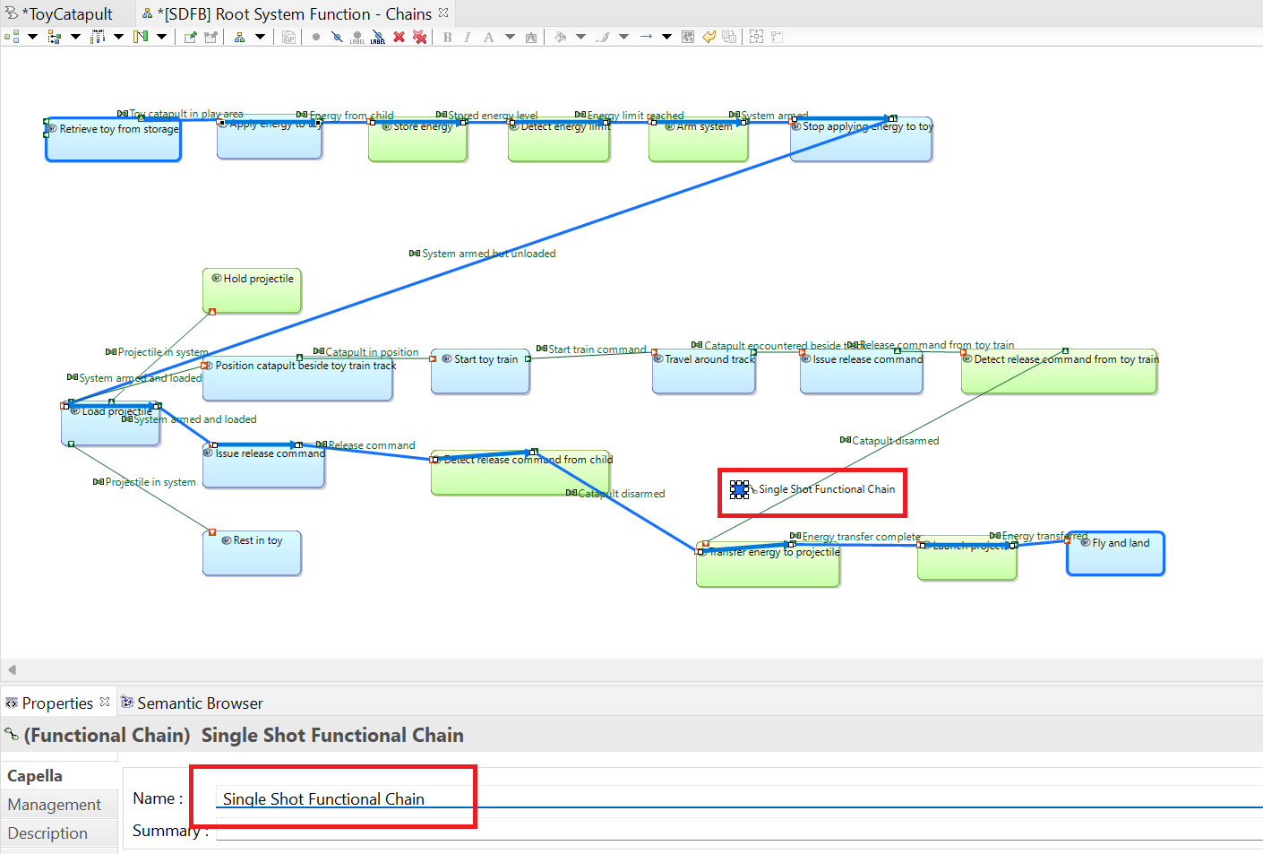
Select all of the functional exchanges along the path from Retrieve toy from storage to Fly and land
running through the function Detect release command from child.
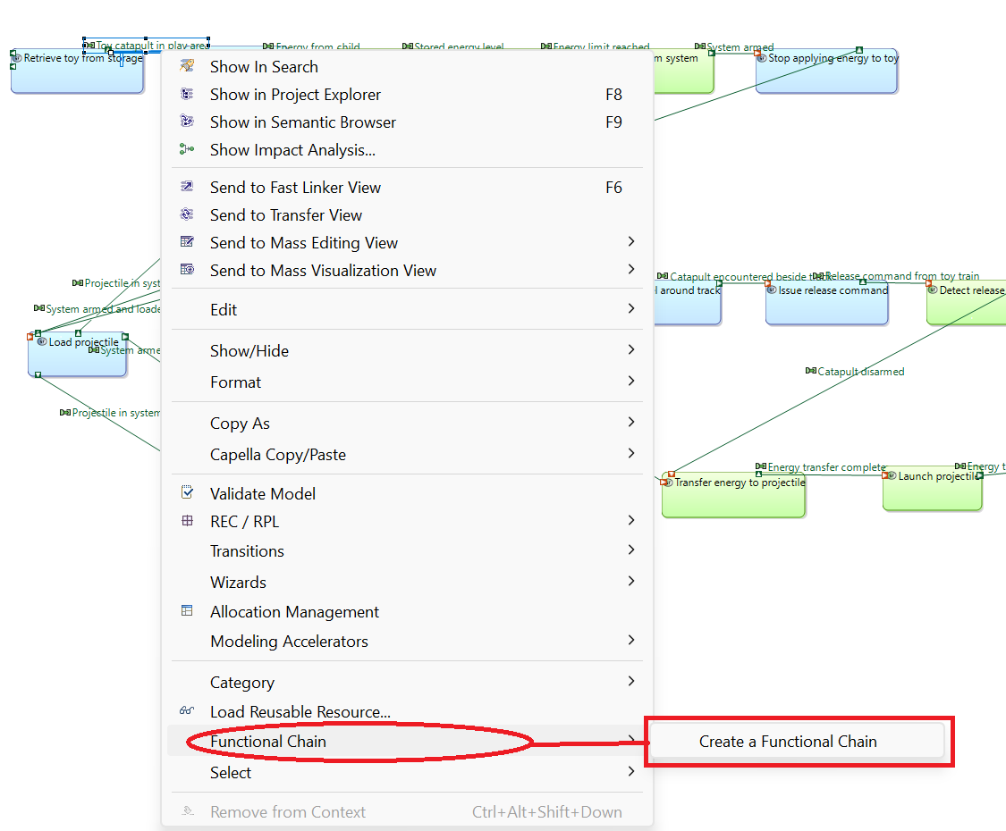
Right-click on any one of the selected functional exchanges and select the Functional Chain → Create a Functional Chain menu item.
If the menu item is not visible, it is likely because your selection of functional exchanges does not satisfy the rules to be a functional chain.
Perhaps you missed selecting one of the connecting exchanges. Try again.
Rename the resulting functional chain as Single Shot Functional Chain. Note that a label for the functional chain has been added to the diagram.
Repeat the previous step, this time selecting all of the functional exchanges along the path from Retrieve toy from storage to Fly and land
running through the function Detect release command from toy train.
Right-click any one of the functional exchanges and create a functional chain, naming it Train Shot Functional Chain.You may have to move the resulting label so that it is more visible.
We have successfully added two functional chains to the model which describe common sequences of functions.
Our scenario analysis has led to some detailed functional requirements.
In this section, we show how you can collect similar functions together, using an affinity technique, and represent them with a higher level function.
The result is a functional hierarchy, or what Capella calls a System Function Breakdown.
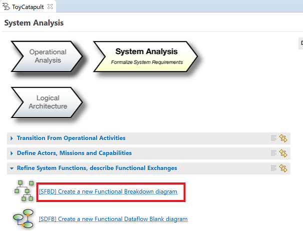
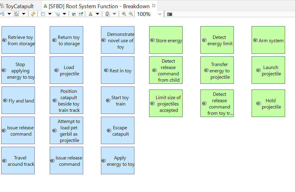
Click [SFBD] Create a new Functional Breakdown diagram in the System Analysis
tab of the workflow. Name it [SFBD] Root System Function - Breakdown
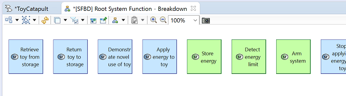
All system functions have been added to the diagram automatically, creating quite a wide layout.
For a more compact diagram, organize the functions into two groups:
actor-allocated functions (functions which have been allocated to actors outside of the system), and
system-allocated functions (functions which have been allocated to the system).
Observe that actor-allocated functions are colored blue and system-allocated functions are colored green.
The order of functions within the groups is not important.
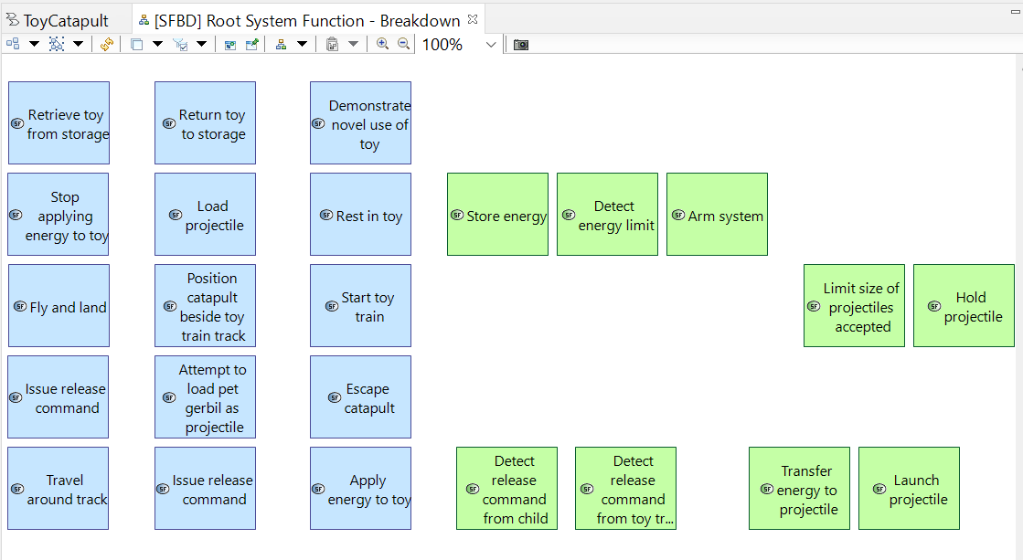
Next use an affinity technique (dragging and dropping entries into collections which share some affinity with each other) on just the system-allocated functions.
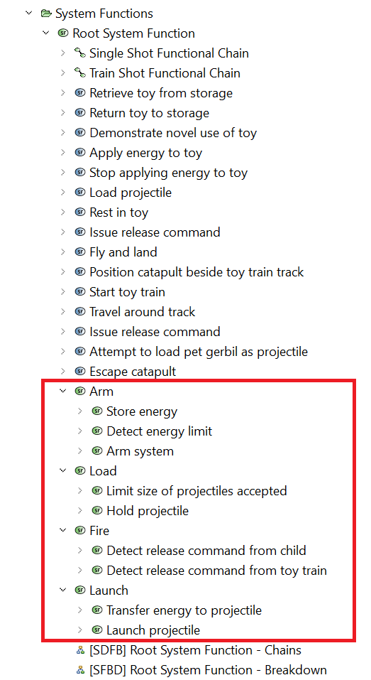
Use the System Function tool in the Palette to add four new functions:
Arm, Load, Fire, and Launch.
These new functions are high-level functions which we will use to summarize the affinity groups.
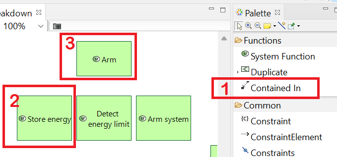
(1) Click the Contained in tool in the Palette, (2) click the Store energy
function, and (3) click the Arm function.
This creates the relation that Store energy is contained in the Arm function.
By definition, now, the Arm function is an aggregate, or higher order function.
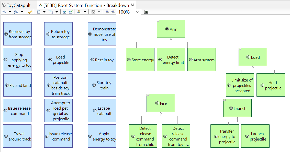
Repeat the previous step to create "contained in" relations for each of the affinity groups.
Observe that the functional hierarchy is captured in the model, as shown in the Project Explorer.
Observe that, as part of system analysis, we have completed a "Dive and Surface" cycle. That is, we used scenario analysis to "dive" into detail
to understand system requirements, but then we "surfaced," using the affinity technique, to achieve a higher level view of our system. The ability to surface and
present a bird's-eye view of your system is an important skill. Capella allows you to communicate your design at many different levels.
We are now ready to produce the final product of this design phase, namely the System Architecture diagram.
In this section, we will not create new modeling objects, unless we find we have missed something.
Instead, we will be organizing the existing objects within the architecture diagram.
The architecture diagram is an integrative representation of our system analysis.
Developing this organization might take some time. There is no one correct organization, but, it is important to come up with a clear representation.
You may follow the organization we propose below, or you may create your own view.
Click [SAB] Create a new System Architecture diagram in the System Analysis tab of the workflow.
Rename or save the diagram as [SAB] Toy Catapult System.
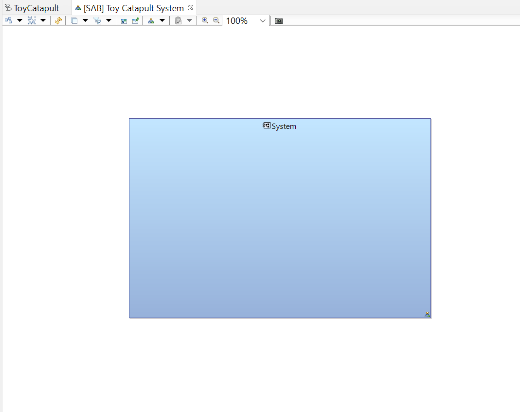
Your diagram displaying only the System will be opened. Move the System block to the center and
enlarge it.
Double-click on the title of the tab header to maximize the diagram window.
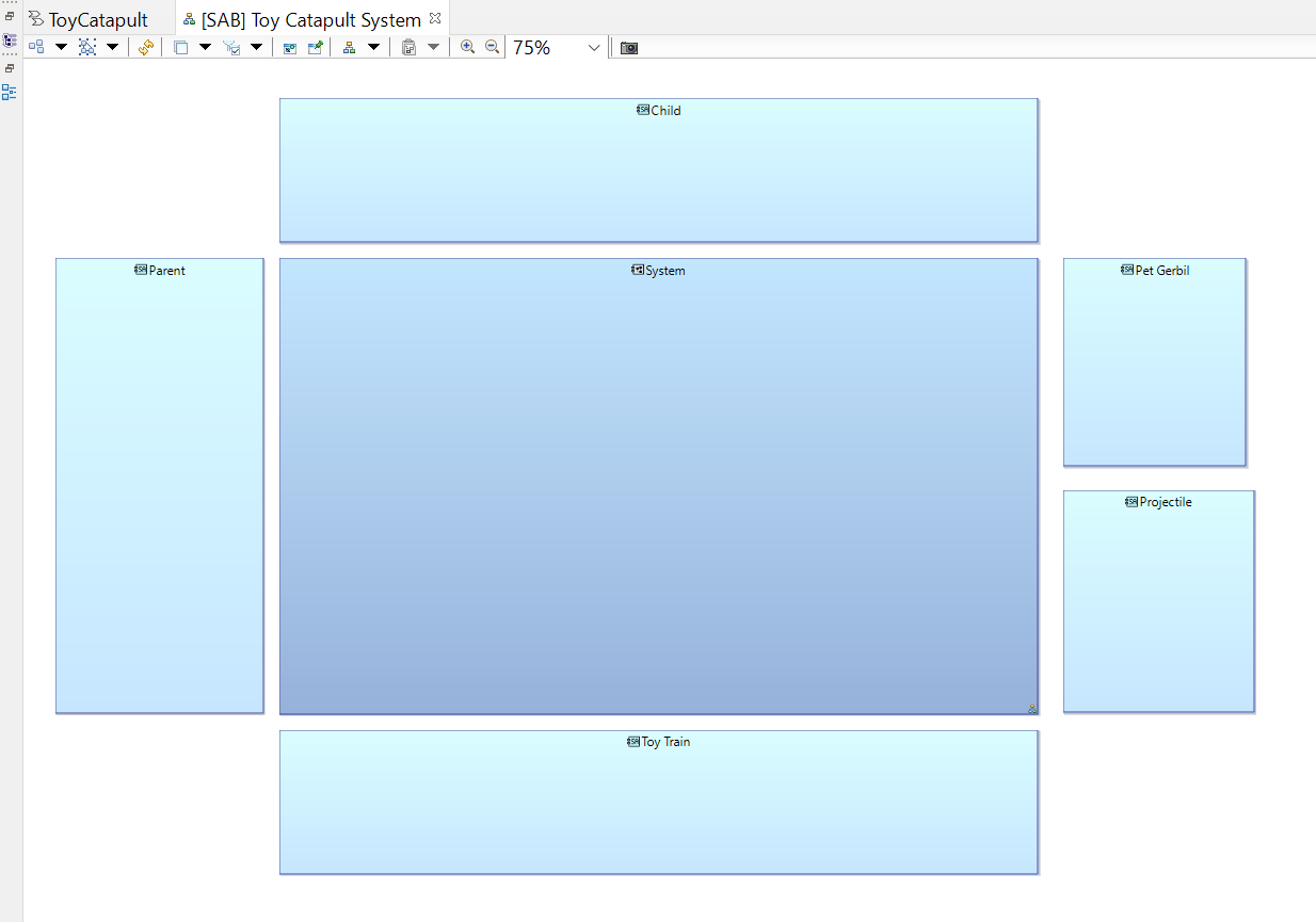
Use the Actors tool in the Palette to add all actors (except the Toy actor) to the diagram.
We suggest arranging the resulting blocks in the pattern below. Be generous in the size of your blocks (note that this is a 75% view) as we have many
functions to add, particularly in the Child block.
In the steps which follow, we are going to add existing functions to one actor at a time. If you add them all at once you will have a confusing mess. It
is best to proceed progressively from the simple to the complex. We will introduce formatting tricks as we go.
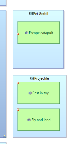
Use the Allocated Functions tool in the Palette to add functions to the Pet gerbil block.
Select all available functions (there is only one). Use the handles on the function box to resize it to make the text readable.
Use the Allocated Functions tool in the Palette to add functions to the Projectile block.
Select all available functions (there are only two). Move them so that they do not overlap.
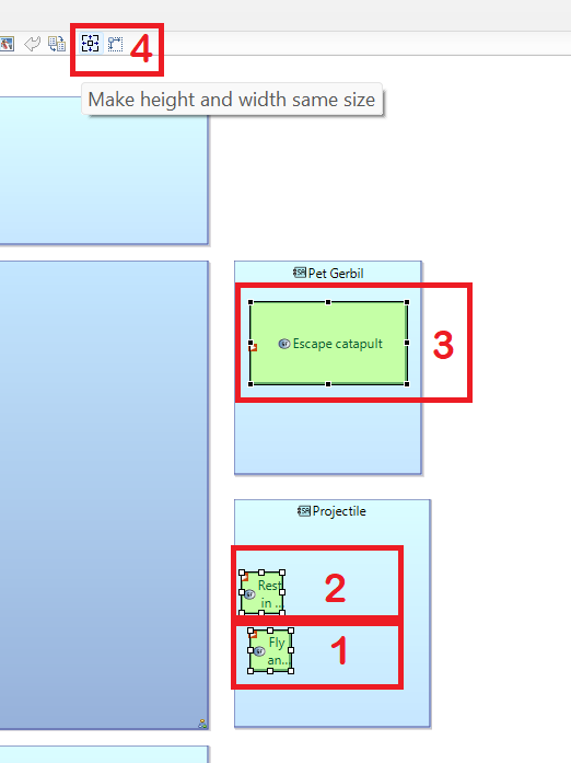
We would like these new function boxes to have the same size as the Escape catapult box. Use this trick:
(1) Select the Fly and land box, then, holding down the Ctrl key, (2) select the Rest in toy box, and
3) select the Escape catapult box. It is important to select the Escape catapult box last as it has the styling we want to mimic.
Finally, (4) click the Make height and width same size button on the window menu.
Now, all function boxes are the same size. You will need to use this trick repeatedly as we proceed.
Use the Allocated Functions tool in the Palette to add functions to the Parent block.
Select all available functions but exclude the Demonstrate novel use of toy. Move them so that they do not overlap.
Use the trick from the previous step to make these function boxes have the same size and height as the Escape catapult box.
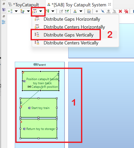
We would like these new function blocks to be evenly spread out vertically. Use this trick:
(1) Using the Ctrl key, select each of the functions in the Parent block, then
(2) click the Distribute Gaps Vertically button on the window menu.
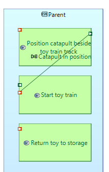
Now, all function boxes are the same size and nicely arranged. (I also used the "Align Left" tool.)
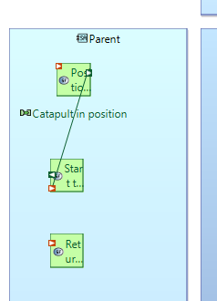
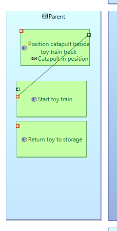
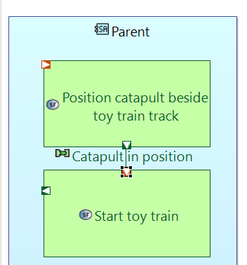
The functional exchange Catapult in position doesn't look nice. The connector has an output port on the right side
of the Position catapult beside toy train track function box and
an input port on the left side of Start toy train function box. Drag the input and output ports so that the connector has
a better appearance.
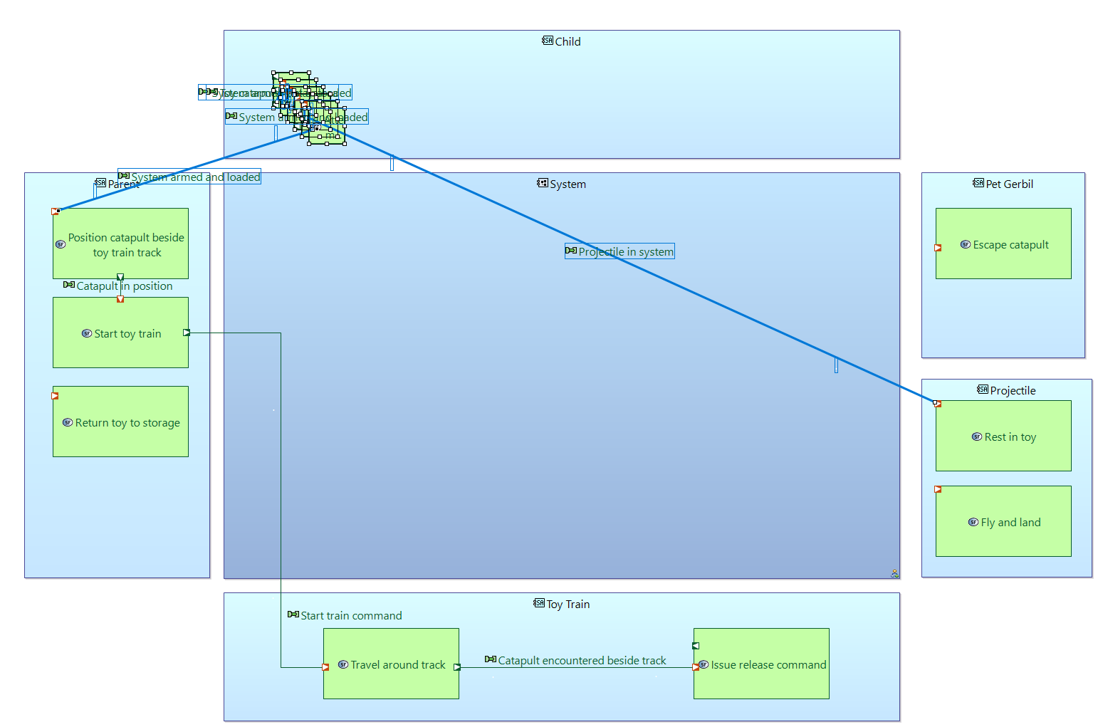
Use the Allocated Functions tool in the Palette to add functions to the Toy train block.
Select all available functions (there are only two). Use the various tricks you have learned to size and arrange the function boxes and to position ports.
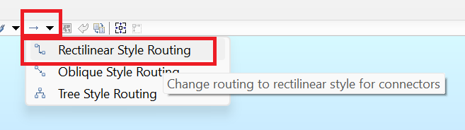
Deselect everything by clicking in some open space of the diagram. Then click Select All Connectors.
With all connectors selected, click Rectilinear Style Routing from the window menu.
Drag the line segments of the connectors and the connector labels to create a more readable diagram. You will use this trick repeatedly.
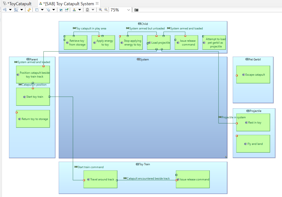
Use the Allocated Functions tool in the Palette to add functions to the Child block.
Select all available functions (there are many).
Now use all of the tricks you have learned to improve the appearance of the diagram. Note that we have made the Child
function boxes a little smaller to fit horizontally.
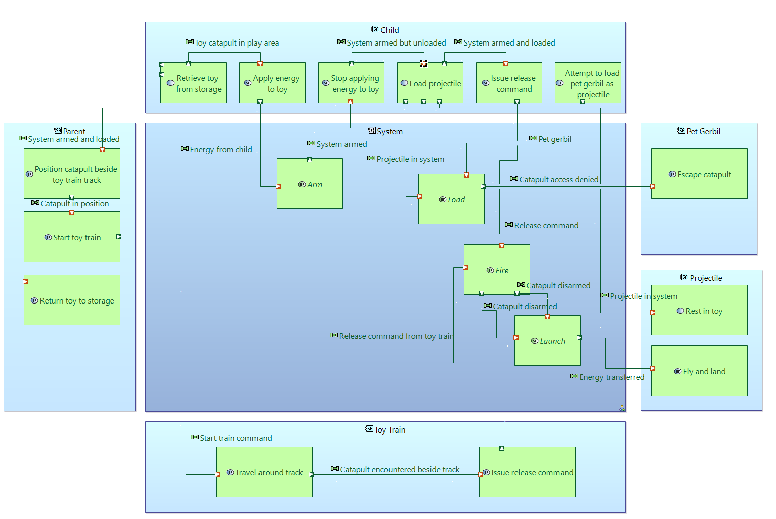
The final set of functions to add are System functions. Use the Allocated Functions
tool in the Palette to add functions to the System block.
Select all available functions (there are many).
The surprise here is that only the high-level functions (Arm, Load, Fire, and Launch)
were added to the diagram. You can repeat this step and select exactly the mix of high- and low-level functions you want to appear on the
diagram. We will stick with just the high-level functions.
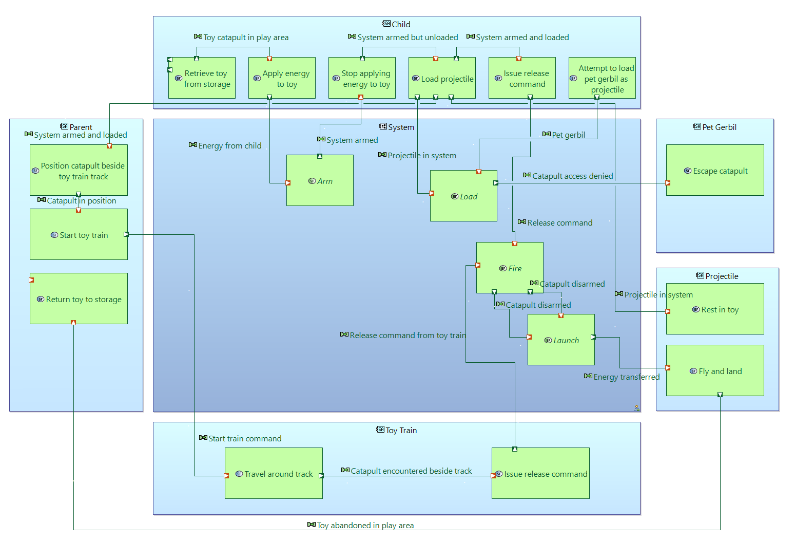
Again, use all of the tricks you have learned to improve the appearance of the diagram.
Observe that the high-level function boxes are drawn with a dotted outline.
Looking at this diagram, we spot that the function Return toy to storage is isolated: we neglected to add any interaction with it during
our scenario analysis. We can easily fix that now. Using the Functional Exchange tool,
add a connection from the Fly and land function to the Return toy to storage function. Rename it Toy abandoned in play area.
Use formatting techniques to make it attractive.
This is our completed architecture diagram for the Toy Catapult System.
You can create as many architecture diagrams as you want, depending on what viewpoint you want to convey to your audience. To illustrate this,
we will clone the Toy Catapult System diagram twice in order to show the functional chains we created in the previous section.
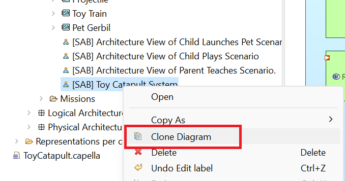
In the Project Explorer right-click on the entry for the Toy Catapult System diagram
and click on the Clone Diagram option.
Right-click on the newly created entry and rename it as
Toy Catapult System Single Shot Chain. Double-click on the renamed diagram to open it.
Click on Functional Chains in the Palette and click in the open space in the upper left of the diagram.
Select the Single Shot Functional Chain. The chain will be highlighted in the diagram and a label will be added. Move the
label wherever you like.
Repeat the previous step, creating a new clone of the Toy Catapult System diagram and re-naming it Toy
Catapult System Train Shot Chain. Using the Functional Chains tool, add the Train Shot Functional Chain.
These last three architectural diagrams provide a nice summary of the System Analysis phase. We move next to the
Logical Architecture phase.
Today's world has thus increased in complexity and interdependence to a point where the traditional methods of problem solving based on the cause-and-effect model cannot cope any longer.
Pidd, M. (2004). Systems Modelling. Wiley.
Systems Thinking is a discipline for seeing wholes.
It is a framework for seeing interrelationships rather than things;
for seeing patterns of change rather than static 'snapshots'.
…
Today systems thinking is needed more than ever because we are becoming overwhelmed by complexity.
Senge, P. M. (2006). The fifth discipline: The art and practice of the learning organization. Broadway Business.
 Click the Systems Analysis chevron, or its corresponding tab at the bottom of the panel.
 Locate and click the Contextually create new System Actors from Operational Entities/Actors button.
 In the resulting dialog, (1) select all of the actors and operational entities, and (2) click OK.
 In the next dialog, click the Apply button.
 No new diagram is created, but by using the Project Explorer, you can see that the transition has created four system functions
and four system entities/ actors.
No new diagram is created, but by using the Project Explorer, you can see that the transition has created four system functions
and four system entities/ actors.
 The Semantic Browser is composed of three panels. In the center panel, we see the Current Element, which is the Parent actor and any elements it may own.
On the right, we observe Referenced Elements.
Here we see the system functions Demonstrate novel use of toy and Return toy to storage
which have been created automatically (based on their counterparts in Operational Analysis).
We also see that they have been
allocated automatically to the Parent actor. We also see a link back to the Operational Actor Parent
which gave rise to the System Actor.
Finally, on the left, we observe Referencing Elements.
This panel will show diagrams and elements which reference the Parent actor.
There are no such diagrams or elements yet.
The Semantic Browser is composed of three panels. In the center panel, we see the Current Element, which is the Parent actor and any elements it may own.
On the right, we observe Referenced Elements.
Here we see the system functions Demonstrate novel use of toy and Return toy to storage
which have been created automatically (based on their counterparts in Operational Analysis).
We also see that they have been
allocated automatically to the Parent actor. We also see a link back to the Operational Actor Parent
which gave rise to the System Actor.
Finally, on the left, we observe Referencing Elements.
This panel will show diagrams and elements which reference the Parent actor.
There are no such diagrams or elements yet.
 Rename as [CSA] System Context and click OK.
Your diagram will be created and opened.
Rename as [CSA] System Context and click OK.
Your diagram will be created and opened.
 Firstly, we observe that the System element has been added automatically, as it is the focus of this design phase.
We sometimes use the phrase system of interest to distinguish this focal system from other systems which may be mentioned.
In our mind, the system of interest is the toy catapult we are developing.
Secondly, all of the system actors have been added to the diagram and connected to the system of interest.
Firstly, we observe that the System element has been added automatically, as it is the focus of this design phase.
We sometimes use the phrase system of interest to distinguish this focal system from other systems which may be mentioned.
In our mind, the system of interest is the toy catapult we are developing.
Secondly, all of the system actors have been added to the diagram and connected to the system of interest.
 This adds an arrow to the diagram with an open triangle at one end. (We have moved the actor Toy to be closer to the Toy Train.) We read this relationship as "the Toy
is a generalization of the Toy train actor," or, alternatively, "the Toy train
is a specific example of the Toy type of actor."
This adds an arrow to the diagram with an open triangle at one end. (We have moved the actor Toy to be closer to the Toy Train.) We read this relationship as "the Toy
is a generalization of the Toy train actor," or, alternatively, "the Toy train
is a specific example of the Toy type of actor."

 Rename the new actor as Projectile and add an Actor Generalization arrow from
the Projectile actor to the Toy actor as described in an earlier step. (The Projectile is a type of Toy.)
Rename the new actor as Projectile and add an Actor Generalization arrow from
the Projectile actor to the Toy actor as described in an earlier step. (The Projectile is a type of Toy.)
 This completes our System Context diagram. After saving, you may close the tab by clicking the x icon.
 In the next dialog, select Entertain child and parent and click OK.
 In the dialog shown below, simply click the Apply button.
 Using the Project Explorer, locate the newly added mission Entertain Child and Parent.
Using the Semantic Browser, observe that this mission traces back to the Entertain Child and Parent
operational capability (OC).
Using the Project Explorer, locate the newly added mission Entertain Child and Parent.
Using the Semantic Browser, observe that this mission traces back to the Entertain Child and Parent
operational capability (OC).
 Double-click on the mission Entertain Child and Parent and type the following statement into the Summary section:
Amuse a 4-year-old child safely creating an opportunity for parent and child to play together in a way that delights them both. Click the Finish button.
Double-click on the mission Entertain Child and Parent and type the following statement into the Summary section:
Amuse a 4-year-old child safely creating an opportunity for parent and child to play together in a way that delights them both. Click the Finish button.
 In this way, we have captured our aspirational mission statement as part of the system documentation.
 Rename the diagram or save it as suggested ([MB] Missions).
Your diagram will be opened with an empty workspace.
(1) Click on the Missions tool in the Palette, and
(2) click anywhere in the working area.
Recall that the
Rename the diagram or save it as suggested ([MB] Missions).
Your diagram will be opened with an empty workspace.
(1) Click on the Missions tool in the Palette, and
(2) click anywhere in the working area.
Recall that the  icon is used to insert existing modeling objects,
and we already created our system mission.
icon is used to insert existing modeling objects,
and we already created our system mission.
 Select the system mission Entertain Child and Parent in the transfer dialog (not shown) and click OK.
The mission will be added to the diagram.
Select the system mission Entertain Child and Parent in the transfer dialog (not shown) and click OK.
The mission will be added to the diagram.
 Move the actors to appropriate locations by dragging and dropping.
(1) Click on the Actor Involvement tool in the Palette,
(2) click on the mission Entertain Child and Parent, and
(3) click on the Child actor, to define the actor involvement.
Move the actors to appropriate locations by dragging and dropping.
(1) Click on the Actor Involvement tool in the Palette,
(2) click on the mission Entertain Child and Parent, and
(3) click on the Child actor, to define the actor involvement.
 Repeat the process for the Parent.
After you complete this, the mission diagram should look like the image below:
Repeat the process for the Parent.
After you complete this, the mission diagram should look like the image below:
 Close the diagram.
 Rename the diagram or save it as suggested ([MCB] Capabilities).
Your diagram will be opened with an empty workspace.
Add our existing system mission to the diagram by
(1) clicking the Missions tool in the Palette,
(2) clicking anywhere in the diagram,
(3) selecting the existing mission Entertain CHild and Parent in the transfer dialog and clicking OK (as in the previous step).
Rename the diagram or save it as suggested ([MCB] Capabilities).
Your diagram will be opened with an empty workspace.
Add our existing system mission to the diagram by
(1) clicking the Missions tool in the Palette,
(2) clicking anywhere in the diagram,
(3) selecting the existing mission Entertain CHild and Parent in the transfer dialog and clicking OK (as in the previous step).
 We will now define three new capabilities.
In order to define our first capability,
(1) click the Capability tool in the Palette, and
(2) click anywhere in the working area.
We will now define three new capabilities.
In order to define our first capability,
(1) click the Capability tool in the Palette, and
(2) click anywhere in the working area.
 Rename the capability, Capability 1, as Entertain child.
 Next, we will define the relation between our mission and the new capability.
(1) Click the Capability Exploitation tool in the Palette,
(2) click our mission on the diagram, and
(3) click on the new capability.
Next, we will define the relation between our mission and the new capability.
(1) Click the Capability Exploitation tool in the Palette,
(2) click our mission on the diagram, and
(3) click on the new capability.
 The newly-defined capability exploitation will be represented by an arc.
We read this relation as "The mission 'Entertain Child and Parent' exploits the system capability 'Entertain Child.'"
Repeat the process to define two more capabilities (and exploitations):
The newly-defined capability exploitation will be represented by an arc.
We read this relation as "The mission 'Entertain Child and Parent' exploits the system capability 'Entertain Child.'"
Repeat the process to define two more capabilities (and exploitations):

 Rename the diagram [SAB] Architecture View of Child Plays Scenario.
You will see the System actor already located on the diagram.
Rename the diagram [SAB] Architecture View of Child Plays Scenario.
You will see the System actor already located on the diagram.
 Rearrange and resize the blocks on the diagram to look like this:
 That is, our user, the Child actor, is placed to the left of the System, the external entity, the Projectile actor, is placed to the right,
and the boxes are stretched in height to form visual swimlanes.
That is, our user, the Child actor, is placed to the left of the System, the external entity, the Projectile actor, is placed to the right,
and the boxes are stretched in height to form visual swimlanes.
 Note that there are two shortcuts to the Delete from Model command. One is to use the keyboard command CTRL+D and the other is to
click the double-X button on the menu bar:
Note that there are two shortcuts to the Delete from Model command. One is to use the keyboard command CTRL+D and the other is to
click the double-X button on the menu bar:
 Confirm the deletion by clicking "Yes" in the resulting dialog. Note that the function Play with toy has not only disappeared from
the diagram but it has also disappeared from the list of system functions in the Project Explorer.
The interaction Toy moved to play area has also been deleted from the model.
Confirm the deletion by clicking "Yes" in the resulting dialog. Note that the function Play with toy has not only disappeared from
the diagram but it has also disappeared from the list of system functions in the Project Explorer.
The interaction Toy moved to play area has also been deleted from the model.
 Observe that we have not specified how energy is to be stored or what mechanism will be used to arm the system. Those design decisions are
deferred until a deeper level of analysis. But you see basic functional requirements of the system emerging from this analysis.
Observe that we have not specified how energy is to be stored or what mechanism will be used to arm the system. Those design decisions are
deferred until a deeper level of analysis. But you see basic functional requirements of the system emerging from this analysis.
 Name the resulting functional exchange Toy catapult in play area. Choose the line style Rectilinear Style Routing.
 Rename the new diagram as [SAB] Architecture View of Parent Teaches Scenario.
 Reposition the Parent block between the Child and the System blocks
and the Toy train block on the far right. Resize the blocks for symmetry.
Reposition the Parent block between the Child and the System blocks
and the Toy train block on the far right. Resize the blocks for symmetry.
 Note our convention that we place users to the left of the System and supporting entities to the right.

 In the resulting dialog, select the Entertain child system capability and click OK.
 In the following dialog, name the diagram Child Plays Scenario. The diagram should appear pre-loaded with a timeline
for the System.
In the following dialog, name the diagram Child Plays Scenario. The diagram should appear pre-loaded with a timeline
for the System.
 Our convention in these sequence diagrams is to put the user timeline to the left of the system timeline and to put all other supporting actors to the right.
Rearrange the timelines according to this convention:
Our convention in these sequence diagrams is to put the user timeline to the left of the system timeline and to put all other supporting actors to the right.
Rearrange the timelines according to this convention:

 Similarly add all of the System and Projectile system functions.
 In the resulting Create a Message dialog, select the existing functional exchange Toy catapult in play area and click OK.
 Resize the vertical box created on the timeline so that it spans the Apply energy to toy state fragment.

 The next images show the resulting Child Plays Scenario diagram.

 This note has no role in the model. It is a graphical addition to the diagram to help its readability. Add another note at
the bottom of the diagram reading "The ending state for this scenario is initiation of the 'Transfer energy to projectile' action in the Child Plays Scenario."
This note has no role in the model. It is a graphical addition to the diagram to help its readability. Add another note at
the bottom of the diagram reading "The ending state for this scenario is initiation of the 'Transfer energy to projectile' action in the Child Plays Scenario."


 Name the diagram [SDFB] Root System Function - Chains. Then use the Functions tool to add all
functions to the diagram except the following:
Name the diagram [SDFB] Root System Function - Chains. Then use the Functions tool to add all
functions to the diagram except the following:
 The result is a mess: all of the functions have been added on top of each other.
 While all of the functions are still selected, as a group, click the Arrange Selection menu item.
 The result is a more logical layout of the functions.
 The diagram layout is quite large.
Note that the Palette includes tools to zoom in and out of diagrams.
If your mouse has a wheel, then Ctrl+Wheel can be used to zoom in and out as well.
The draggable viewport in the Outline window is also useful for panning around the view.
The diagram layout is quite large.
Note that the Palette includes tools to zoom in and out of diagrams.
If your mouse has a wheel, then Ctrl+Wheel can be used to zoom in and out as well.
The draggable viewport in the Outline window is also useful for panning around the view.

 Note also that you can select groups of functions (and their connecting exchanges) by dragging a rubber-band box around the group.
Use zooming, selection, and dragging to create a more compact view of the functions.
Note also that you can select groups of functions (and their connecting exchanges) by dragging a rubber-band box around the group.
Use zooming, selection, and dragging to create a more compact view of the functions.

 Select all of the functional exchanges along the path from Retrieve toy from storage to Fly and land
running through the function Detect release command from child.
Select all of the functional exchanges along the path from Retrieve toy from storage to Fly and land
running through the function Detect release command from child.
 Right-click on any one of the selected functional exchanges and select the Functional Chain → Create a Functional Chain menu item.
If the menu item is not visible, it is likely because your selection of functional exchanges does not satisfy the rules to be a functional chain.
Perhaps you missed selecting one of the connecting exchanges. Try again.
Right-click on any one of the selected functional exchanges and select the Functional Chain → Create a Functional Chain menu item.
If the menu item is not visible, it is likely because your selection of functional exchanges does not satisfy the rules to be a functional chain.
Perhaps you missed selecting one of the connecting exchanges. Try again.
 Rename the resulting functional chain as Single Shot Functional Chain. Note that a label for the functional chain has been added to the diagram.

 All system functions have been added to the diagram automatically, creating quite a wide layout.
 For a more compact diagram, organize the functions into two groups:
 These new functions are high-level functions which we will use to summarize the affinity groups.
 This creates the relation that Store energy is contained in the Arm function.
By definition, now, the Arm function is an aggregate, or higher order function.
This creates the relation that Store energy is contained in the Arm function.
By definition, now, the Arm function is an aggregate, or higher order function.

 Observe that the functional hierarchy is captured in the model, as shown in the Project Explorer.
 Rename or save the diagram as [SAB] Toy Catapult System.
Your diagram displaying only the System will be opened. Move the System block to the center and
enlarge it.
Rename or save the diagram as [SAB] Toy Catapult System.
Your diagram displaying only the System will be opened. Move the System block to the center and
enlarge it.
 Double-click on the title of the tab header to maximize the diagram window.

 We would like these new function boxes to have the same size as the Escape catapult box. Use this trick:
(1) Select the Fly and land box, then, holding down the Ctrl key, (2) select the Rest in toy box, and
3) select the Escape catapult box. It is important to select the Escape catapult box last as it has the styling we want to mimic.
Finally, (4) click the Make height and width same size button on the window menu.
We would like these new function boxes to have the same size as the Escape catapult box. Use this trick:
(1) Select the Fly and land box, then, holding down the Ctrl key, (2) select the Rest in toy box, and
3) select the Escape catapult box. It is important to select the Escape catapult box last as it has the styling we want to mimic.
Finally, (4) click the Make height and width same size button on the window menu.
 Now, all function boxes are the same size. You will need to use this trick repeatedly as we proceed.
 Use the trick from the previous step to make these function boxes have the same size and height as the Escape catapult box.
 We would like these new function blocks to be evenly spread out vertically. Use this trick:
(1) Using the Ctrl key, select each of the functions in the Parent block, then
(2) click the Distribute Gaps Vertically button on the window menu.
We would like these new function blocks to be evenly spread out vertically. Use this trick:
(1) Using the Ctrl key, select each of the functions in the Parent block, then
(2) click the Distribute Gaps Vertically button on the window menu.
 Now, all function boxes are the same size and nicely arranged. (I also used the "Align Left" tool.)
 The functional exchange Catapult in position doesn't look nice. The connector has an output port on the right side
of the Position catapult beside toy train track function box and
an input port on the left side of Start toy train function box. Drag the input and output ports so that the connector has
a better appearance.
The functional exchange Catapult in position doesn't look nice. The connector has an output port on the right side
of the Position catapult beside toy train track function box and
an input port on the left side of Start toy train function box. Drag the input and output ports so that the connector has
a better appearance.
 Deselect everything by clicking in some open space of the diagram. Then click Select All Connectors.
 With all connectors selected, click Rectilinear Style Routing from the window menu.
 Drag the line segments of the connectors and the connector labels to create a more readable diagram. You will use this trick repeatedly.

 Now use all of the tricks you have learned to improve the appearance of the diagram. Note that we have made the Child
function boxes a little smaller to fit horizontally.
Now use all of the tricks you have learned to improve the appearance of the diagram. Note that we have made the Child
function boxes a little smaller to fit horizontally.
 The surprise here is that only the high-level functions (Arm, Load, Fire, and Launch)
were added to the diagram. You can repeat this step and select exactly the mix of high- and low-level functions you want to appear on the
diagram. We will stick with just the high-level functions.
Again, use all of the tricks you have learned to improve the appearance of the diagram.
The surprise here is that only the high-level functions (Arm, Load, Fire, and Launch)
were added to the diagram. You can repeat this step and select exactly the mix of high- and low-level functions you want to appear on the
diagram. We will stick with just the high-level functions.
Again, use all of the tricks you have learned to improve the appearance of the diagram.
 Observe that the high-level function boxes are drawn with a dotted outline.
 This is our completed architecture diagram for the Toy Catapult System.
 Right-click on the newly created entry and rename it as
Toy Catapult System Single Shot Chain. Double-click on the renamed diagram to open it.
Right-click on the newly created entry and rename it as
Toy Catapult System Single Shot Chain. Double-click on the renamed diagram to open it.
 Click on Functional Chains in the Palette and click in the open space in the upper left of the diagram.
Select the Single Shot Functional Chain. The chain will be highlighted in the diagram and a label will be added. Move the
label wherever you like.
Click on Functional Chains in the Palette and click in the open space in the upper left of the diagram.
Select the Single Shot Functional Chain. The chain will be highlighted in the diagram and a label will be added. Move the
label wherever you like.

