After completing the steps in this section, we will have an Operational Architecture
that defines high-level interactions among actors/entities and the system capabilities they require.
We will be using the word "model" to refer to all of the entities and relationships, diagrams and architectures created in this project.
With apologies, this is a very long chapter. We must teach both concepts and techniques. Future chapters are shorter because you will have mastered the techniques.
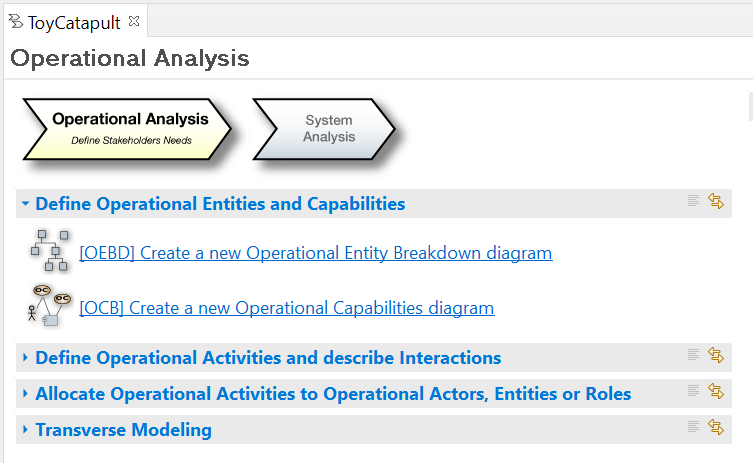
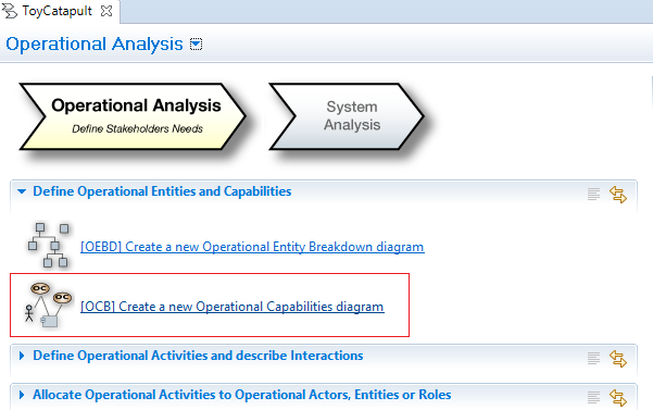
The available diagram types for this design stage can be observed on the Operational Analysis
tab of the Workflow.
Click on the Operational Analysis button or tab at the Workflow.
You will see the possible diagrams under four categories.
You may expand/collapse the categories by clicking the triangle icons.
As briefly explained in the previous section, the aim of this project is to allow the parent
and the child to play and spend time together.
Therefore, we have two actors/entities at the current stage.
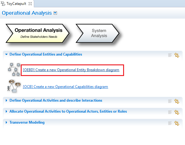
Click on [OEBD] Create a new Operational Entity Breakdown diagram on the
Operational Analysis tab of the Workflow.
You will be prompted a dialogue to enter a name for the diagram.
The name can be anything convenient for you.
Note that you may have multiple diagrams of the same type with different names.
At this step, we will name the diagram as suggested:
[OEBD] Operational Entities and click OK.
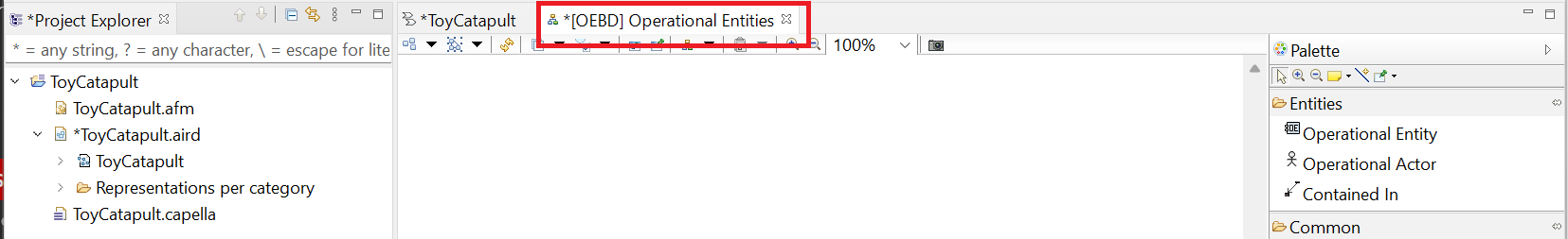
An empty diagram with the given name will be opened and focused.
Notice the * sign on the left of the diagram name,
as well as on the ToyCatapult workflow.
This indicates that there has been a change to the model which has not yet been saved.
You may click the save button or CTRL+S to save the updates.
Notice also that there is a Palette panel on the right of the working area.
This palette lists the tools which can be used to modify this specific diagram
(the tools will be different for each diagram type).
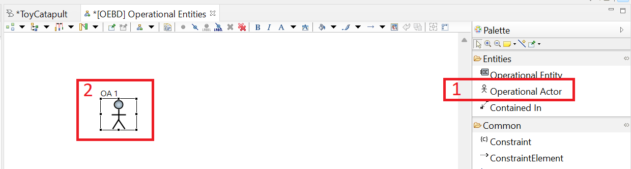
Now we start adding our actors to the model.
(1) Left-click on the Operational Actor tool in the Palette;
then, (2) left-click at anywhere at the working area.
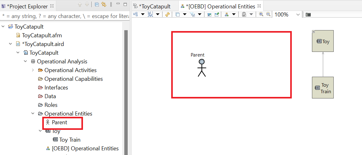
You will see an actor, OA 1 added in the diagram.
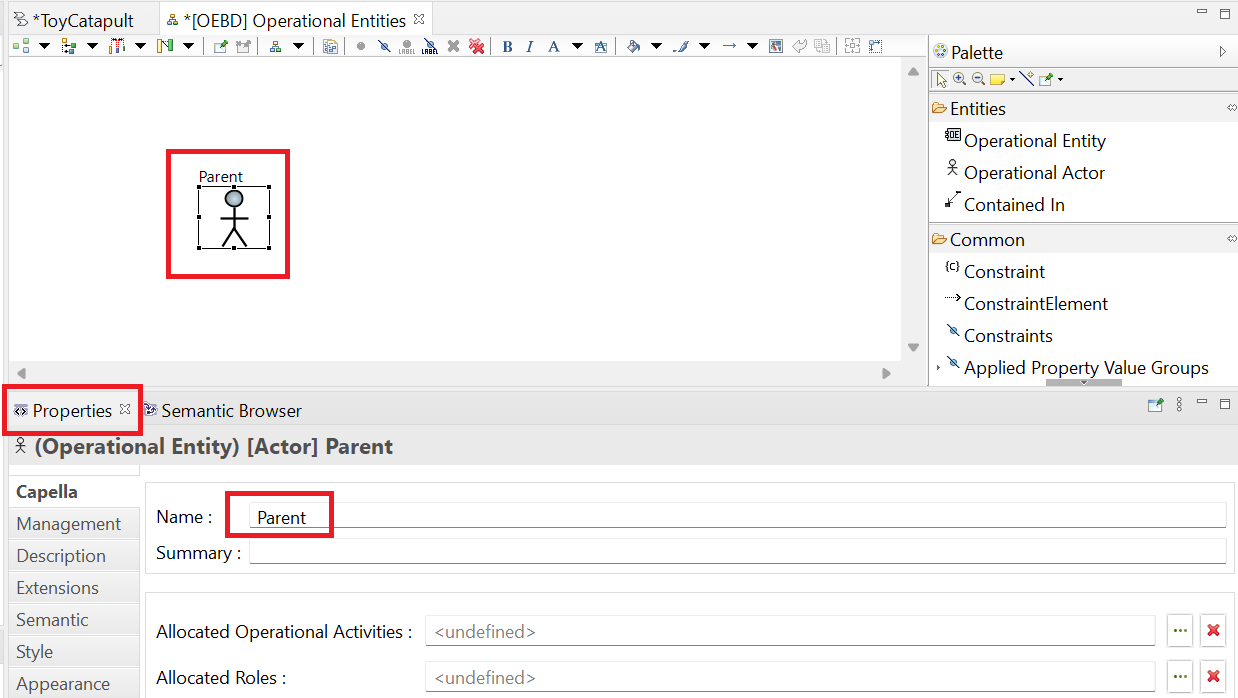
In order to rename our actor; select the actor (left-click the actor in the diagram),
press F2 key, type Parent and press enter.
Alternatively, select the actor, click on the Properties tab at the panel at the bottom,
and change the value of the field Name to Parent.
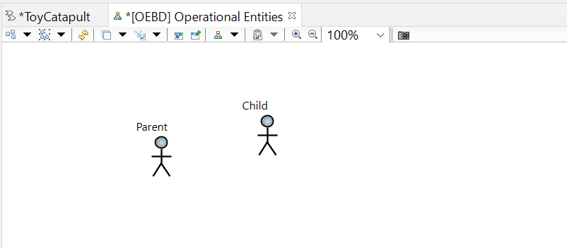
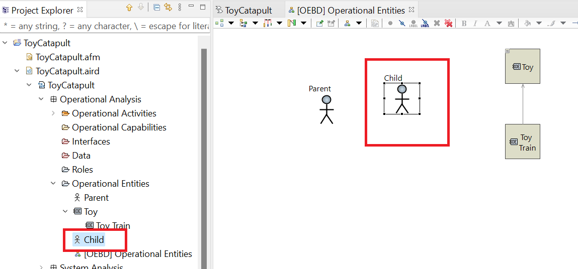
Repeat the previous step for adding the operational actor Child.
Once you are finished, your diagram should look like the following:
The positions of the actor icons are not important in this diagram: you may arrange them as you like.
Notice that we have not used Operational Entity or Contained In tools
in the Palette in this tutorial. They are not needed for this simple design.
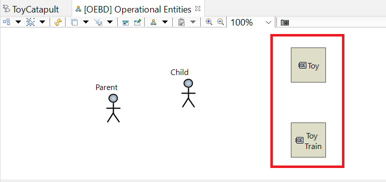
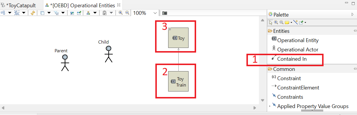
However, you may add operational entities in the same manner as actors; and use the arrows to define containment relationships as
illustrated in the following example.
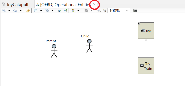
This (optional) example suggests that the parent and child may interact with toys. It provides a sample toy, a toy train, as a particular type of operational entity.
Add the operational entities Toy and Toy Train by following the instructions at Step 2.
Now (1) left-click the Contained In tool in the Palette;
(2) left-click Toy Train in the diagram; and finally
(3) left-click the Toy entity, to state that the toy train operational entity is contained in the toy entity.
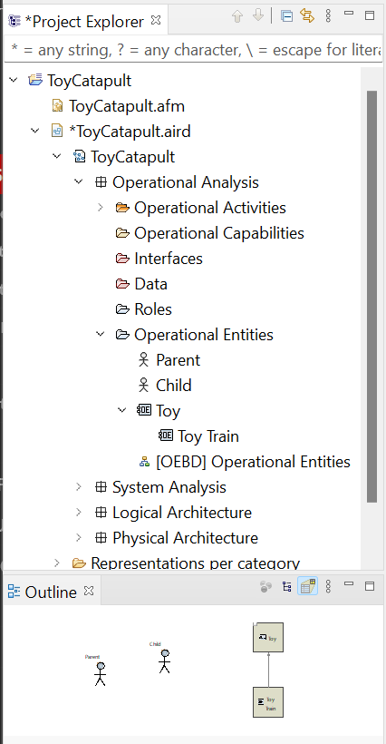
By adding these entities and actors to a diagram, we have also added them to the model.
We can find and view the objects by clicking
ToyCatapult.aird → ToyCatapult → Operational Analysis → Operational Context and
in the Capella Project Explorer.
Whenever you select an object (here, operational actor) in the Capella Project Explorer,
it will be focused and you may view its properties in the Properties window.
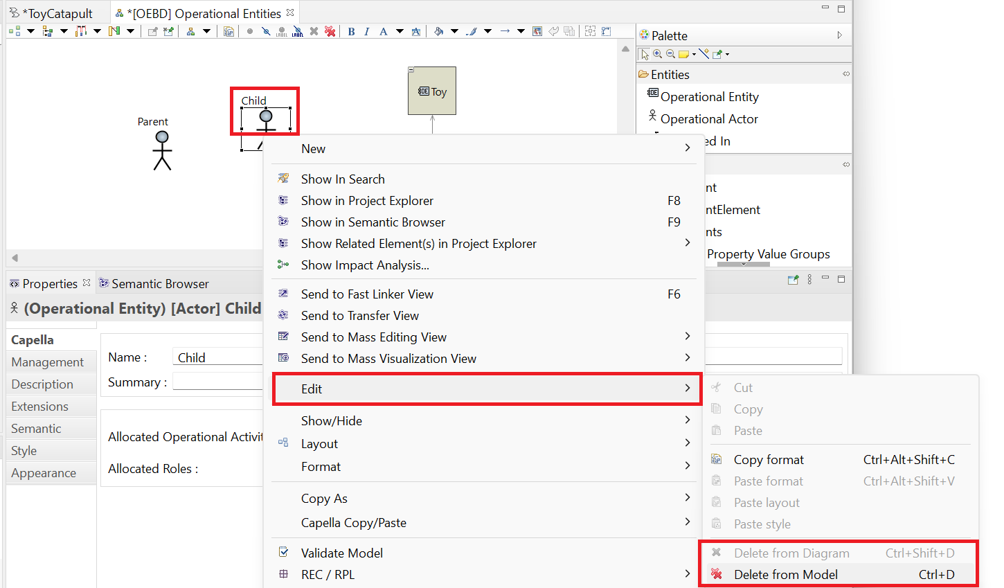
If you delete an object from the model, it will be deleted from every diagram in which it appears. Also, any connections it has with other objects will also be deleted. Sometimes,
you are allowed to delete an object from a diagram but not delete it from the model, and vice versa.
To see your choices, right-click an element in a diagram and select the Edit menu. As an optional example, right-click on the
child actor in the [OEBD] Operational Entities diagram.
As you can see, the option to delete the element from the diagram is greyed out for some reason. However, it is possible to select the
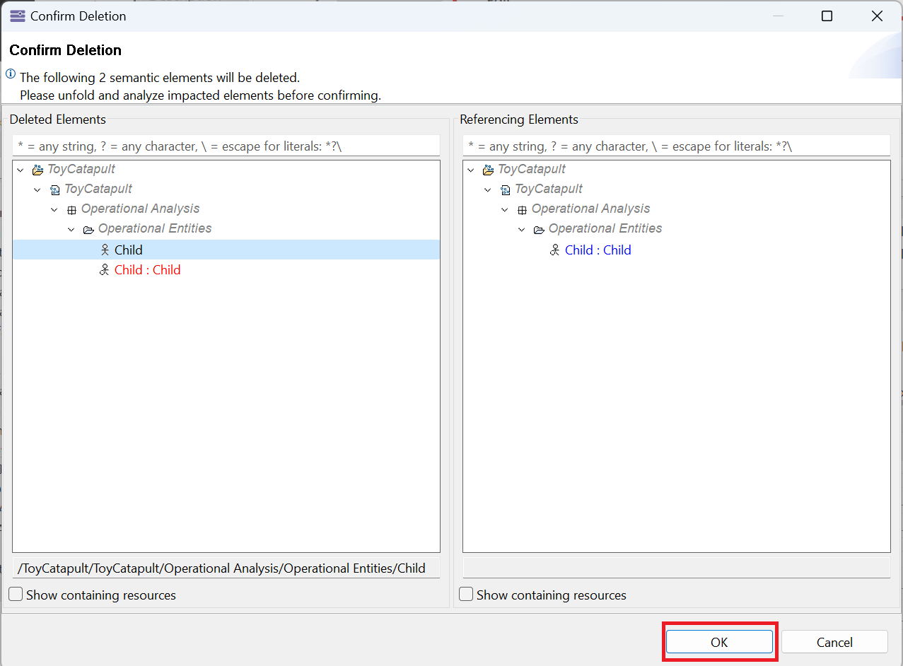
Delete from Model option. Go ahead and select that option. The following dialog should appear warning you of all the model elements which
will be affected by this deletion.
Click OK to approve the deletion. Now, the Child actor has disappeared from the model and from the diagram.
Before proceeding, be sure to add the Child actor back onto the [OEBD] Operational Entities diagram.
(Follow the directions in the previous exercise.)
Notice also the diagram that we created, [OEBD] Operational Entities, is also located under ToyCatapult.aird → ToyCatapult → Operational Analysis → Operational Entities in the Capella Project Explorer.
You may reopen our diagram by double-clicking it here.
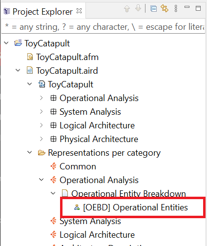
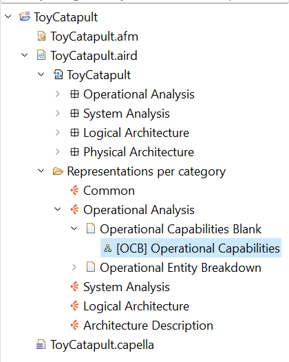
In general, an easier way to find our diagrams is to use the Representations per category section.
Collapse ToyCatapult.aird → ToyCatapult and
click ToyCatapult.aird → Representations per category → Operational Analysis → Operational Entity Breakdown.
Notice that our diagram [OEBD] Operational Entities is located in the folder named as the corresponding diagram type (OEBD).
As we have finished defining our operational entities (and saving our changes: CTRL+S), we may close our diagram by clicking the x icon.
In Jackson, P. L. (2009). Getting design right: a systems approach. CRC Press, we recommended beginning a project with a mission statement.
The mission statement we composed for this project was:
Our mission is to design a toy catapult to amuse a 4-year-old child safely creating an opportunity for parent and child to play together in a way that delights them both.
The Arcadia method recommends starting with a list of operational capabilities. For this example, we will map our mission statement to an operational capability,
Entertain parent and child. We will not make any mention of the chosen solution (a toy catapult) at this stage.
Go back to the Workflow and click
[OCB] Create a new Operational Capabilities diagram.
Accept the suggested diagram name [OCB] Operational Capabilities by clicking OK
(or you might rename it as you like).
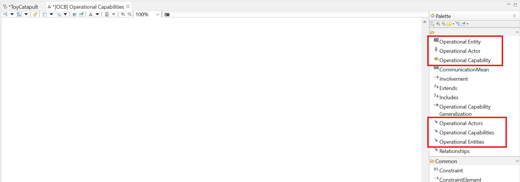
Our empty Operational Capabilities diagram will be created and opened, and the Palette
will be loaded with relevant tools.
It might be confusing to see Operational Entity and Operational Entities
tools in the Palette.
Similarly, we have the plural versions of operational actor and operational capability.
Notice that the plural tools have the same icon on the left: .
There is an important functional difference between the singular and plural versions of the tools, which
will be illustrated in the following step.
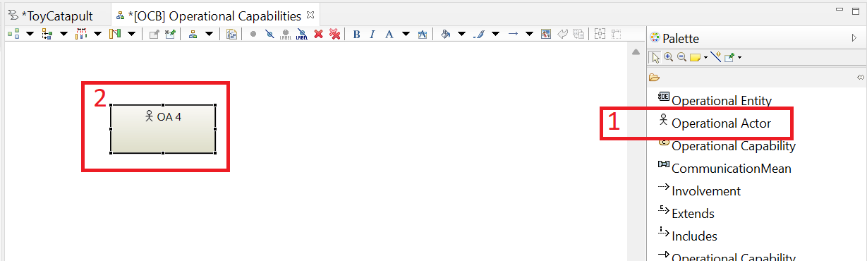
We first use the singular version.
(1) Left-click on the Operational Actor tool in the Palette,
and then (2) left-click on the working area.
You will see that a new operational actor called OA 4 (the number might be different)
is created.
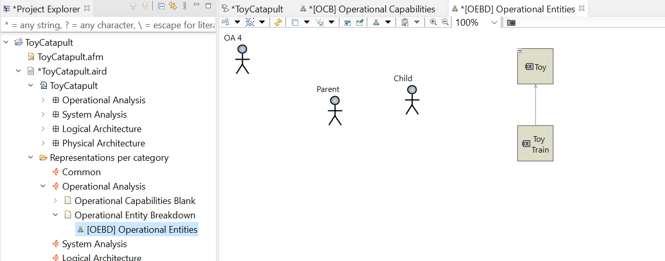
Recall that we have already defined our actors in the operational context (Parent and the Child).
However, with this action, we have defined a new actor.
In order to check, reopen the Operational Entity Breakdown diagram by double-clicking
[OEBD] Operational Entities in
ToyCatapult.aird → Representations per category → Operational Analysis
→ Operational Entity Breakdown
in the Capella Project Explorer.
You will see that the new actor is added to the Operational Entity Breakdown diagram (in a random location).
From this behavior, we see that
Capella provides us with the flexibility to defining an object (such as the Operational Actor here)
in different diagrams; the object will be added to the model no matter where it is created.
Likewise, we can delete an object from different diagrams and it will be deleted from the model.
In this tutorial, we will try to define each object only
in the most relevant diagram (which is the Operational Entity Breakdown for operational actors).
Since we do not want to add another operational actor to the model, let us delete the new actor
OA 4 from either of the [OEBD] Operational Context or
[OCB] Operational Capabilities diagrams by selecting the object, pressing Delete
key and confirming the action by clicking Yes.
Then, close the [OEBD] Operational Context diagram.
At the end, our [OCB] Operational Capabilities diagram needs to be empty again.
We do not want to define new operational actors but use the existing ones.
The tools with plural expression and icon allow us to add existing
objects to the diagrams, as illustrated in the following step.
In this diagram, we want to define new operational capabilities and their relationships with the existing operational
entities or actors.
In order to define a new capability, (1) left-click the Operational Capability tool in the Palette,
and (2) left-click the working area.
Rename OperationalCapability 1 as Entertain Child and Parent by
selecting the object in the diagram, pressing F2 key, typing the new name and pressing Enter key;
or alternatively by (3) updating the Name field in the Properties tab in the bottom panel.
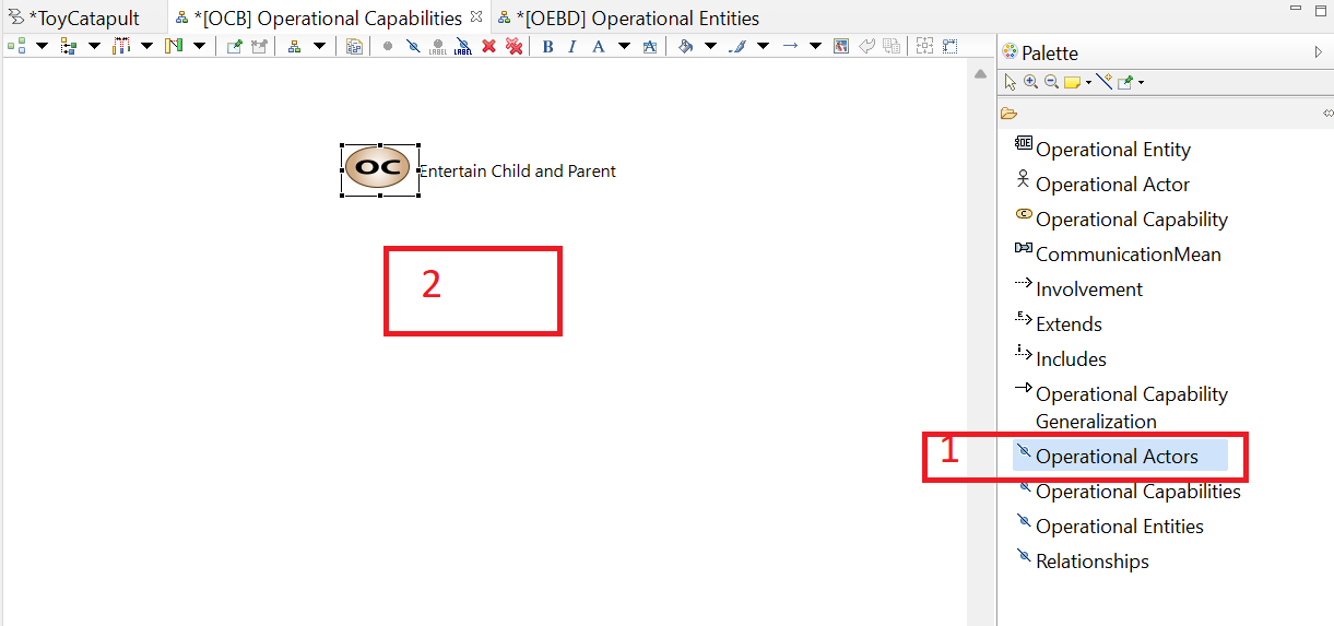
Next, we will define operational capability involvement for the existing actors:
(1) left click Operational Actors tool in the Palette and
(2) left-click on the working area.
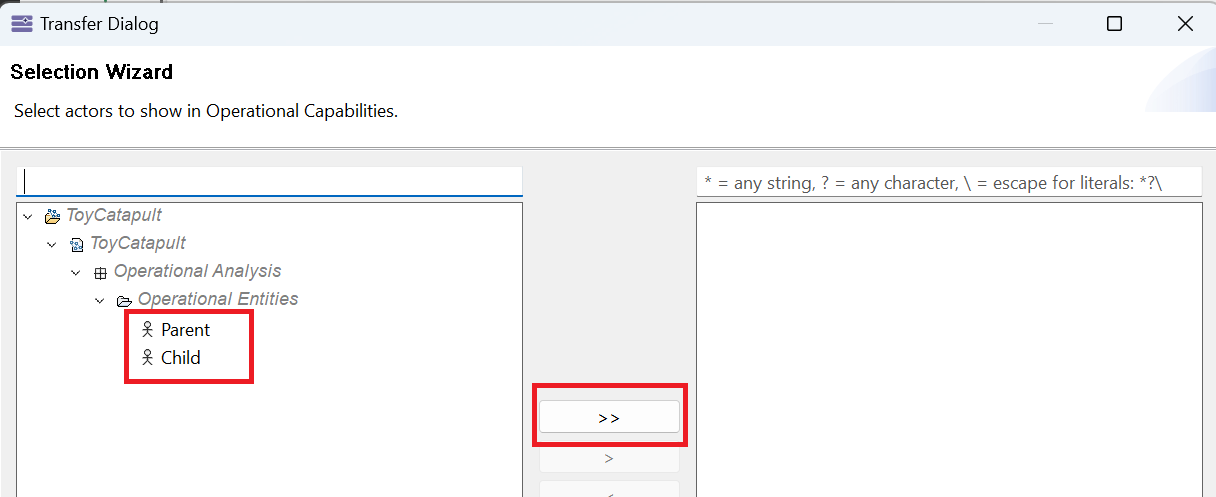
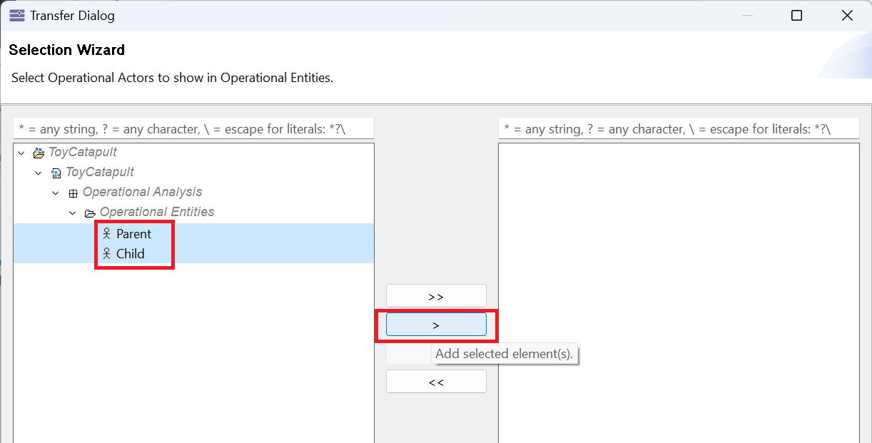
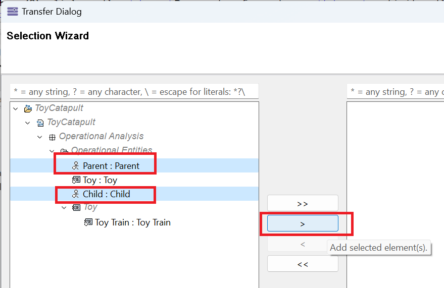
The Transfer Dialog will pop up, displaying the existing operational actors.
Select both actors Child and Parent, and click the > button.
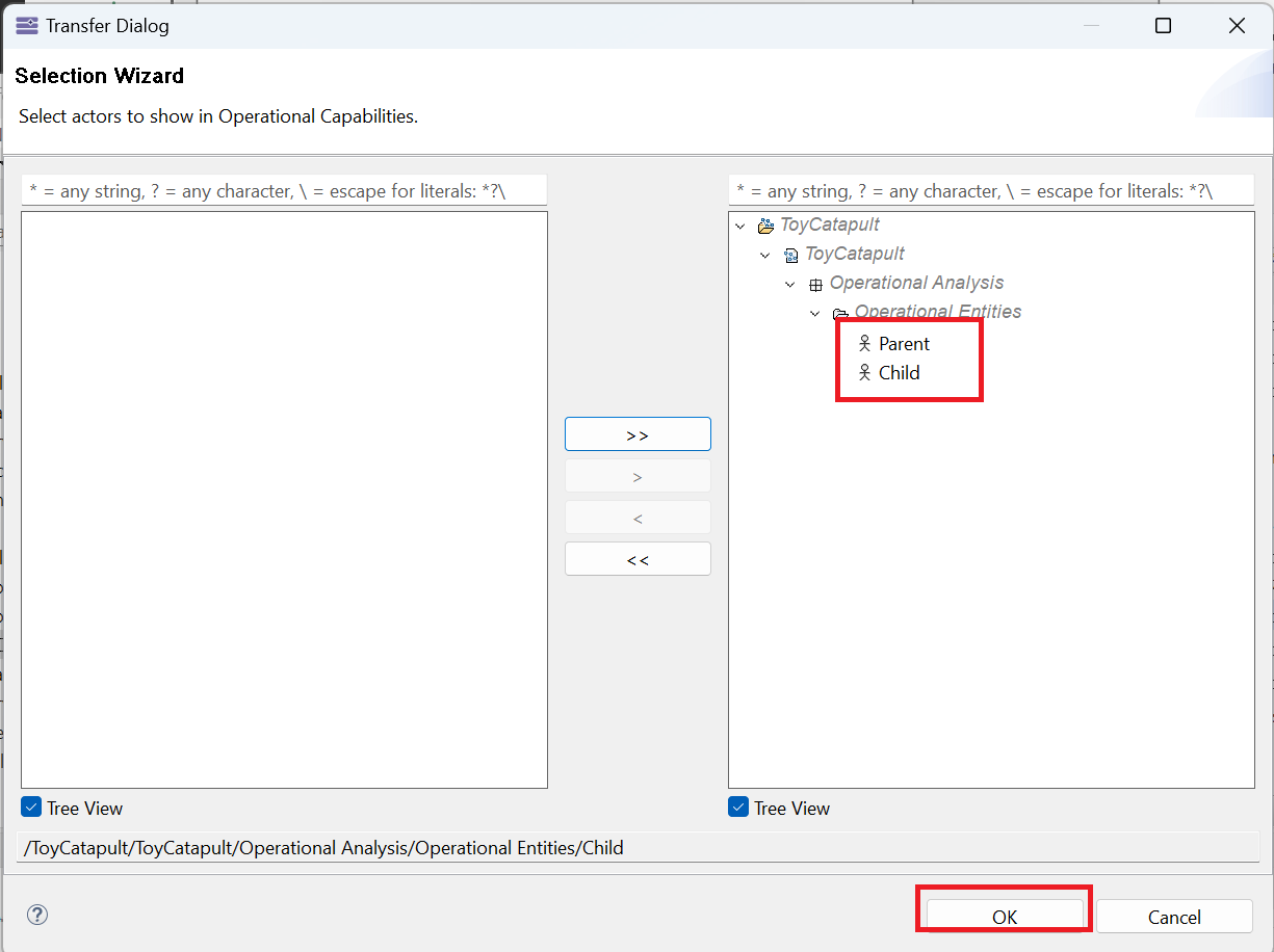
Both actors should be passed to the section on the right, which will be added to the diagram.
Confirm addition by clicking OK.
You should see the actors added to the diagram.
Recall that if we delete an object from a diagram, it will be deleted from the model.
The next step illustrates how to remove an object from a diagram without deleting it from the model
(we may have accidentally added it to the diagram, or we do not want to show it in the diagram for some reason).
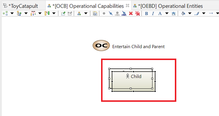
Suppose that we have accidentally added the Child actor in this diagram,
and we want to remove it.
Select the actor in the working area (make sure that only Child is selected).
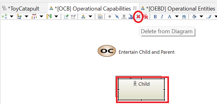
Then, click the Delete from Diagram button.
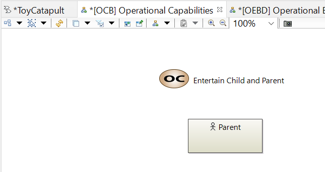
You will see that the object is removed from the diagram without any warning
(this is a sign that we are not actually deleting the object from the model).
You may check the [OEBD] Operational Entities and Actors diagram to see that Child
is not deleted from the model.
Actually, we will need Child actor in this diagram.
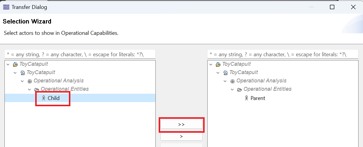
Therefore, let us re-add it by (1) left clicking Operational Actors in the Palette and
(2) left-clicking on the working area.
In the Transfer Dialog, you will see Child on the left panel
(which means that the object exists, but not placed in the diagram); and Parent
on the right panel (meaning that the object is already in the diagram).
Double-click on Child to move it to the right panel, and click OK to confirm.
The object will be re-included in the diagram.
Arrange the positions of the actors by dragging and dropping so that they look similar to the following image.
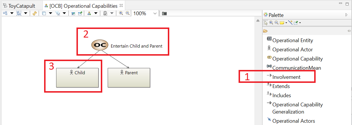
Now, we are ready to define the capability involvements.
(1) Left-click Involvement tool in the Palette,
(2) left-click the operational capability Entertain Child and Parent, and
(3) left-click on the Child actor.
You may arrange the connection points of the involvement arrow by dragging and dropping the black squares on both ends.
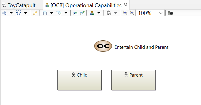
Repeat the same for the Parent actor.
Once you are finished, your diagram should like like the following image.
With this action, we state that the operational capability involves child and parent.
Notice that there exist other types of relationships in the palette, such as extends, includes and capability generalization.
These are relationships between different capabilities (for example "teach physics" might be a plausible way to "extend" the "entertain" capability).
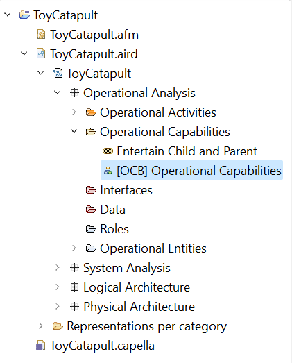
As we have completed (and saved) our operational capability diagram, we may close it by clicking the x icon.
Notice that the diagram and the newly added object, the operational capability, are located in corresponding folders in the Capella Project Explorer.
What does it mean to have an "operational capability"? In the Arcadia method, we illustrate capabilities using "scenarios."
These are sometimes referred to as "use cases" in other methodologies. Every capability must have at least one scenario to explain it.
It is possible to have many scenarios to explain a single capability.
In this project, we use two scenarios to explain what we mean by Entertain Child and Parent.
In the first scenario, we capture the situation in which the child plays with the toy and the parent puts the toy away.
In the second scenario, the parent entertains the child and puts the toy away.
In this section, we will create diagrams and model elements to represent these scenarios.
There are different ways to develop scenarios in Capella.
In whatever way we do it, when we are done we will have activities, allocated to operational entities or actors,
and these activities will have interactions defined between them.
Furthermore, the activities will be organized into sequential processes consistent with these interactions. So, we could follow an approach like the following:
Define the scenario;
Define all the activities;
Allocate the activities to the operational entities or actors;
Define all the interactions; and, then,
Define the operational processes.
In our approach, we will do the first step ("Define the scenario") last.
This is because we prefer to work with Operational Architecture (OAB) diagrams than with Operational Entity Scenario (OES) diagrams.
We can do most of work with OAB diagrams and then finish up with an OES diagram.
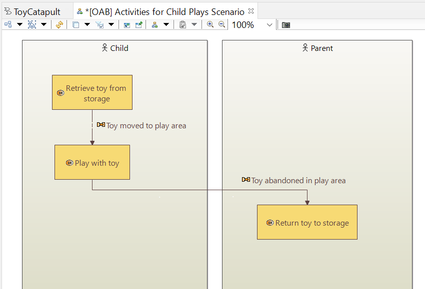
In our first scenario, Child Plays with Toy, we expect the child to retrieve the toy and
play with it.
Finally, once the child stops playing, the parent puts the toy away. We need to define three activities:
Retrieve toy from storage, Play with toy, and Return toy to storage.
We will allocate the first two activities to the Child actor and the third activity to the Parent actor.
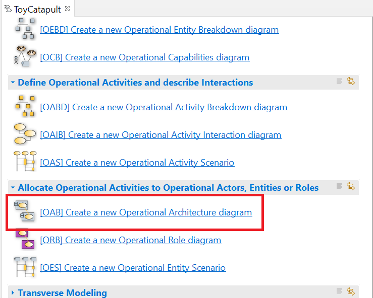
We will use an Operational Architecture (OAB) diagram for this purpose.
Click [OAB] Create a new Operational Architecture diagram in the Workflow.
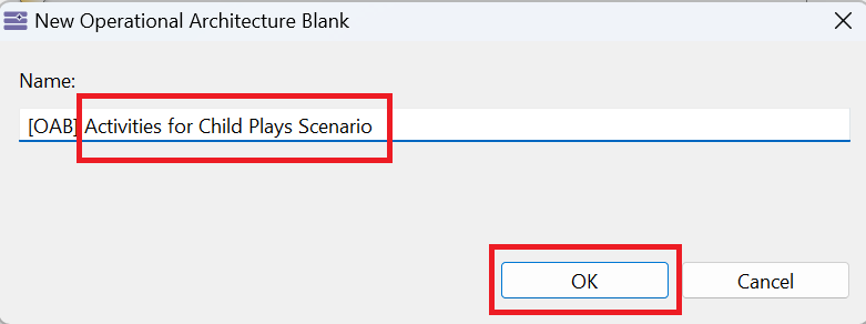
You will be prompted to give a name to the diagram. Call it Activities for Child Plays Scenario and click OK.
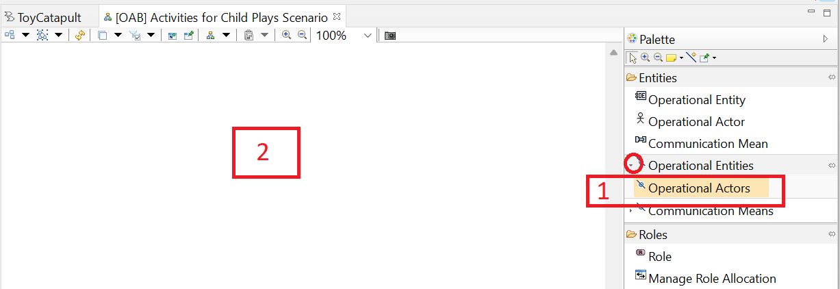
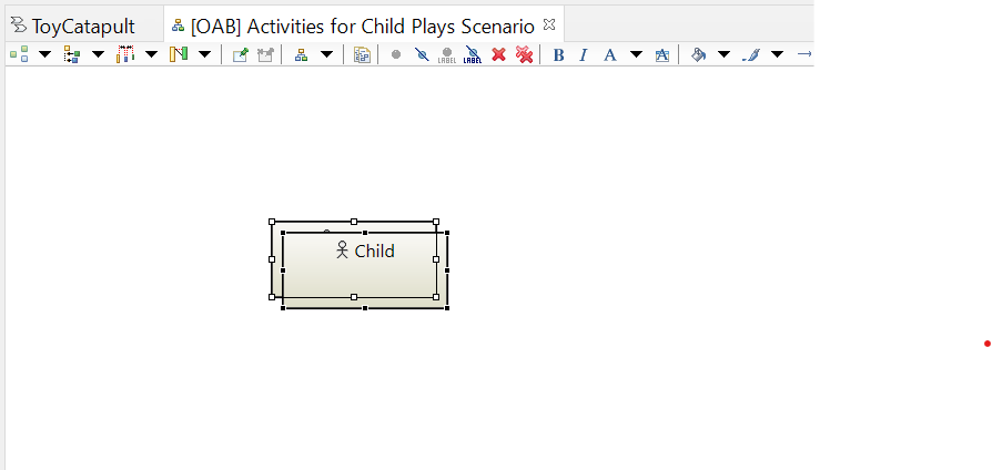
In the resulting diagram, (1) click Operational Actors tool (not Operational Entities... note the expansion icon) in the Palette, then (2) click anywhere in the diagram, and
(3) select both actors Child and Parent, click the > button and then click OK.
The resulting diagram should look like this:
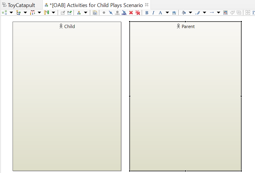
Rearrange and resize the graphical blocks to look like this:
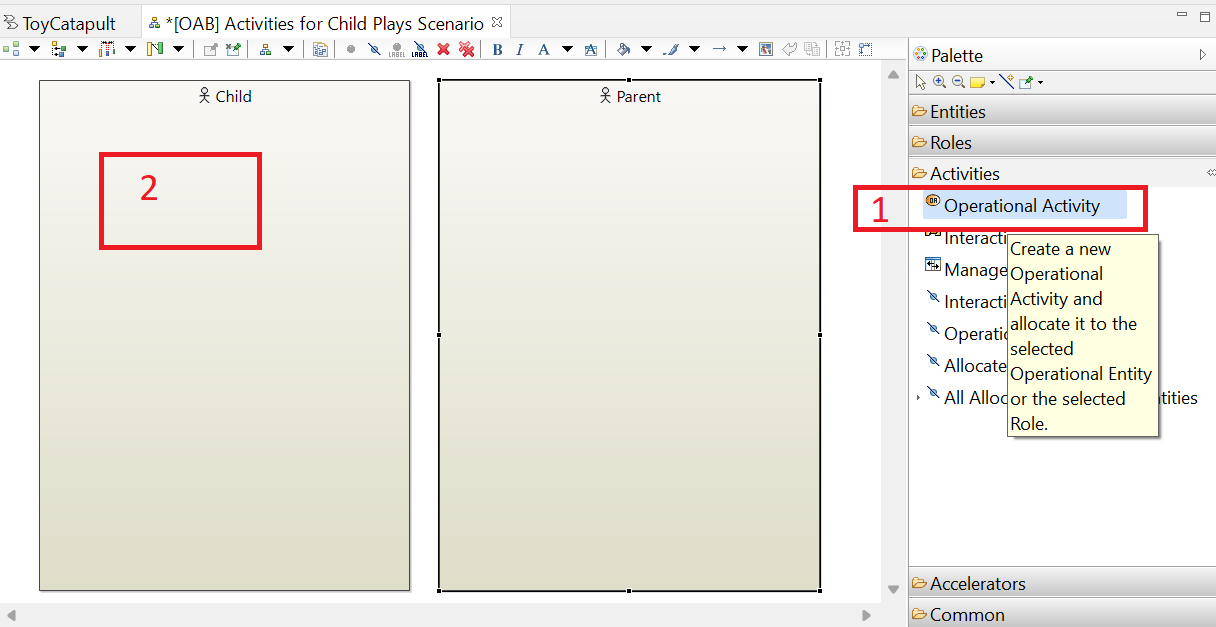
We can use the Palette on this diagram to create activities and, simultaneously, allocate them to actors.
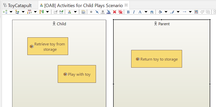
(1) Click the Operational Activity tool and then (2) click anywhere inside the Child block.
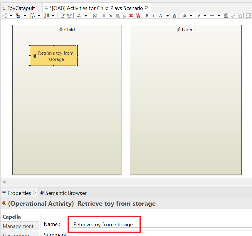
Rename the resulting activity Retrieve toy from storage.
Repeat the previous step, creating an activity Play with toy inside the Child block
and an activity Return toy to storage inside the Parent block.
Next we show how these activities are related to one another by defining interactions. We can think of these as input-output relationships.
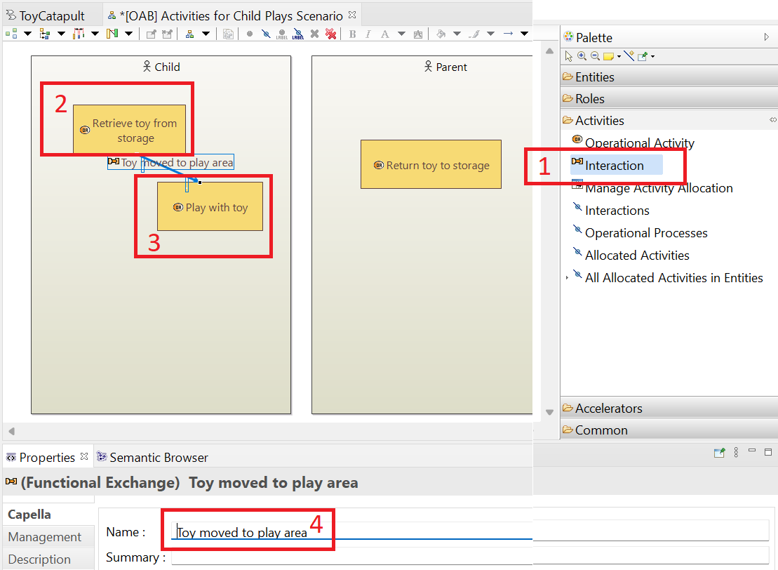
Continue with the "Activities in the Child Plays Scenario" diagram: (1) click the Interaction tool in the Palette,
then (2) click on the Remove toy from storage activity, then (3) click on the Play with toy activity, and finally, (4) change the name of the interaction to Toy moved to play area.
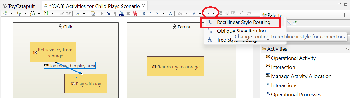
While the interaction is still selected, go to the Line Style menu and choose Rectilinear Style Routing.
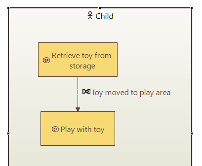
Now for some fussy work. Manipulate the interaction line and label and move the activity blocks until the child section looks like this:
Repeat the process to get an interaction Toy abandoned in play area between the Play with toy activity and the Return toy to storage activity. Fuss with the graphical objects until you have something like this:
By sizing the Operational Entities boxes into vertical swimlanes and by arranging the activities into a vertical sequence, as shown above, we have suggested a certain workflow. This will be made more precise in the next section by defining a scenario.
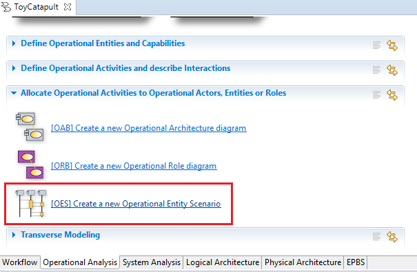
In this section we define a scenario to link our operational activities with the operational capability (our mission) to Entertain Child and Parent.
Click [OES] Create a new Operational Entity Scenario in the Workflow.
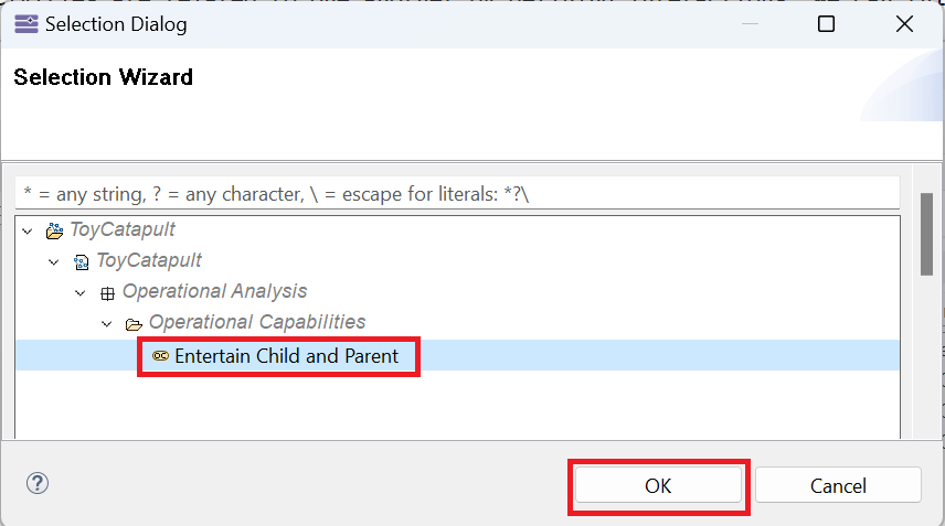
You will be prompted with a dialog to select an operational capability.
This is an intended behavior in Capella which forces us to relate every scenario to an operational capability.
From the Capella perspective, a scenario with no matching operational capability is irrelevant to the project.
Select Entertain Child and Parent and click OK to confirm.
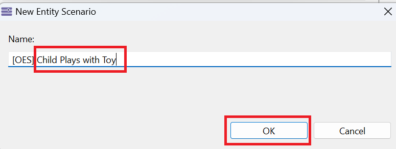
Next, you will be asked to enter a name for the scenario; type [OES] Child Plays with Toy and
click OK.
Your empty scenario will be created.
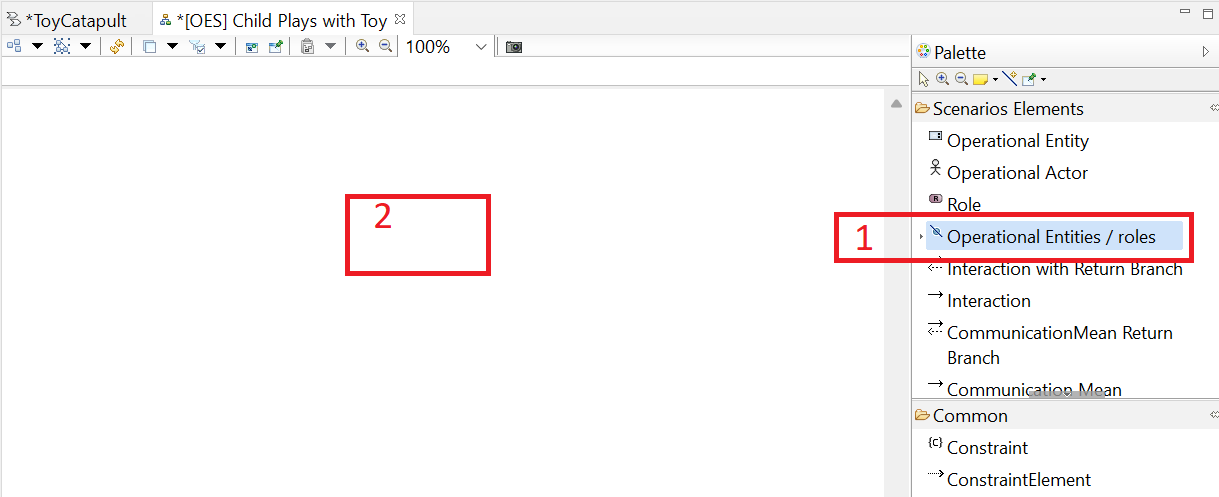
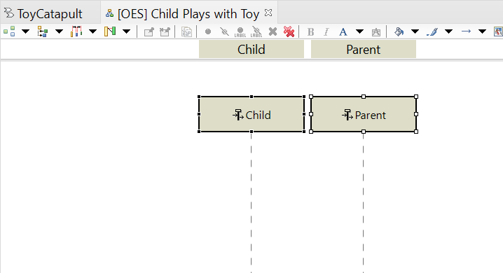
(1) Click Operational Entities / roles tool in the Palette,
(2) click on the working area,
and (3) select both actors Child and Parent, click the > button and then click OK.
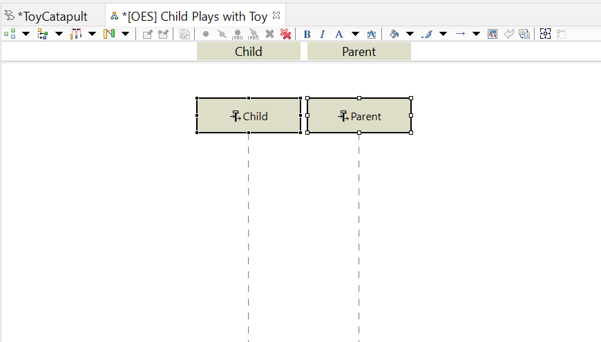
Your scenario diagram should look like the following image.
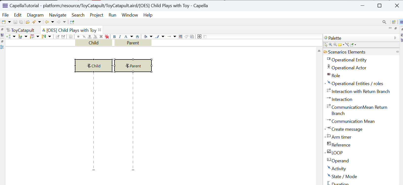
Note in the previous image that the size of the working area is quite small. This will make it uncomfortable to work with so let's enlarge it.
Double-click on the title of the [OES] Child Plays with Toy tab.
You will see that the window size is maximized (hiding left and bottom panels), which is much better while creating the diagram.
You may double-click again to restore the previous size, and unhide the left and bottom panels.
Finally, you may observe the same behavior in all windows on the Eclipse interface (try it with the Properties tab).
Now that you see how to create activities and allocate them to actors, we will return to the Operational Entity Scenario diagram
Child Plays with Toy and use the activities to describe the scenario.
Click on the Child Plays with Toy tab to reactivate the OES diagram. Drag the actor blocks so that the Child block is
in the left-most position. Our convention will be that the left-most column represents the primary actor. Typically, the primary actor is the one
who initiates the scenario.
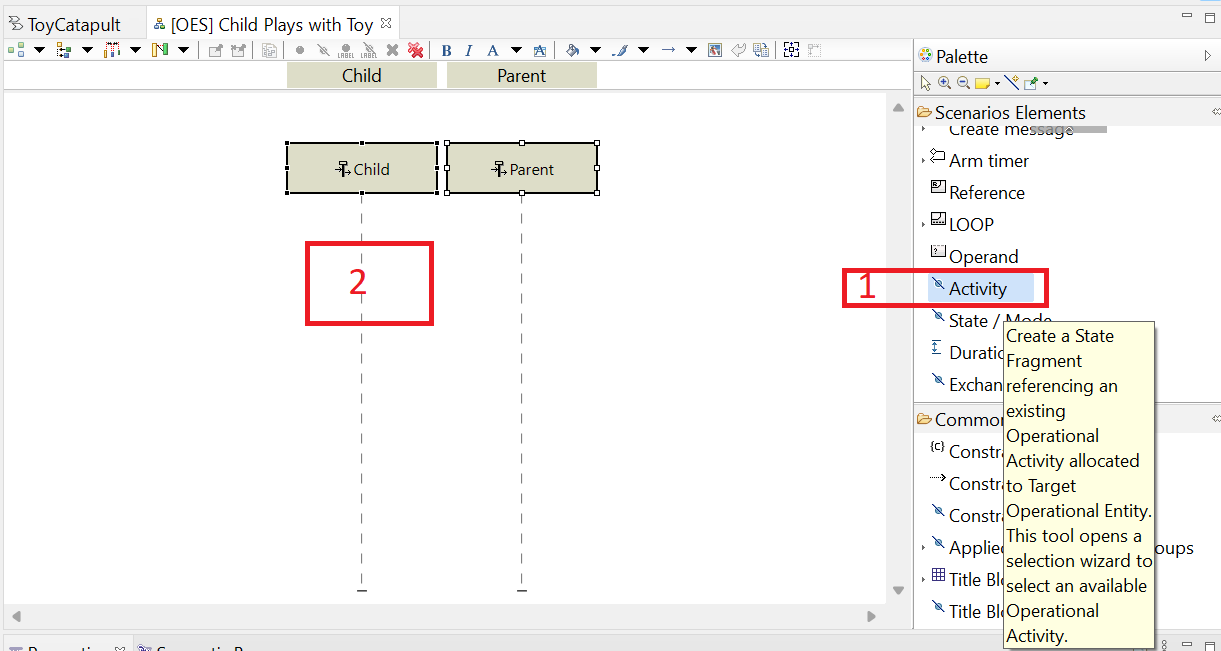
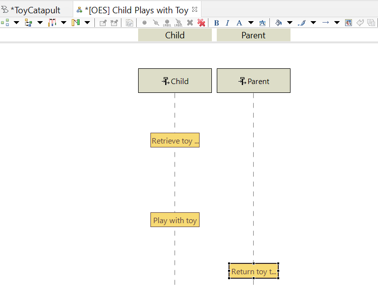
(1) Click on the Activity tool in the Palette and then (2) click on the timeline under the Child block.
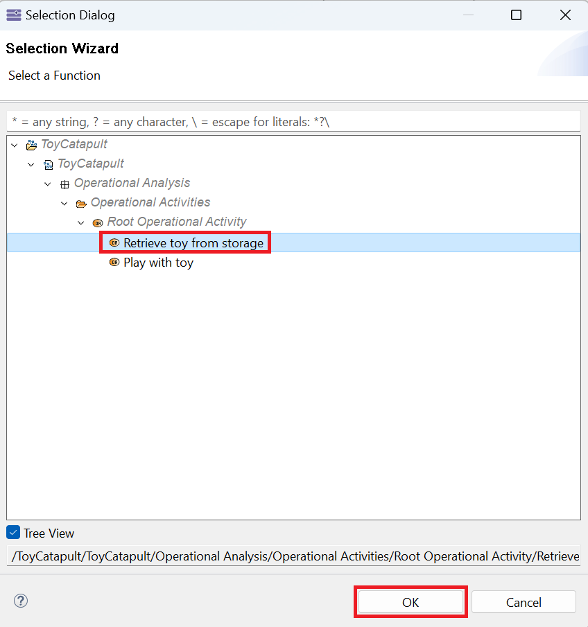
In the selection dialog, select the Retrieve toy from storage activity and click OK.
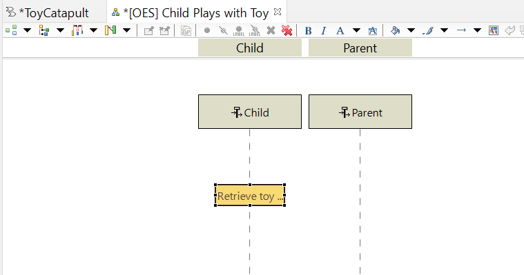
The result is that a State Fragment corresponding to the Retrieve toy from storage activity has been added to the Child timeline.
Technically, the Child is in that state while the activity is being performed.
Repeat the previous step and add state fragments for the Play with toy and Return toy to storage activities.
Now that we have laid out the activities (actually, the state fragments) on the timeline,
the next step is to identify the interactions that occur between these activities.
The transition from one activity to the next is usually marked by some sort of exchange.
It could be a signal that the previous activity has completed. It could be a request for information or service.
Or, it could be some physical transfer or transformation. What marks the transition from the child retrieving the toy and the child playing with the toy?
Well, the toy is now in the play area and ready for use so that is a form of physical transformation (the location coordinates have changed).
We will capture that by adding an interaction called Toy moved to play area.
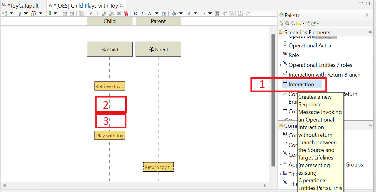
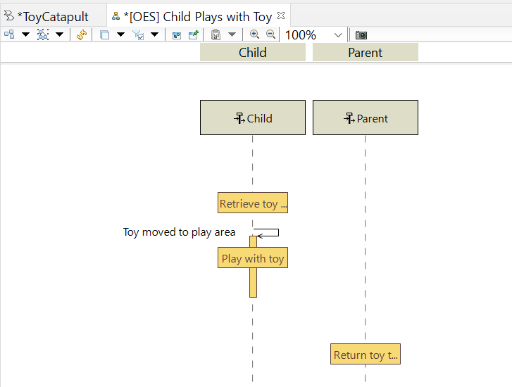
(1) Click on the Interaction tool in the Palette, then (2) click on the Child timeline
between the two state fragments, and (3) click a second time in the same place.
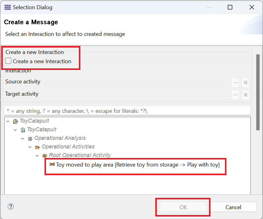
In the resulting dialog, define the interaction by (1) giving it a name, Toy moved to play area,
(2) selecting the source activity Retrieve toy from storage and
(3) selecting the target activity Play with toy.
The selections can be made by clicking the associated elipsis ("...") button and responding to the resulting dialog (not shown).
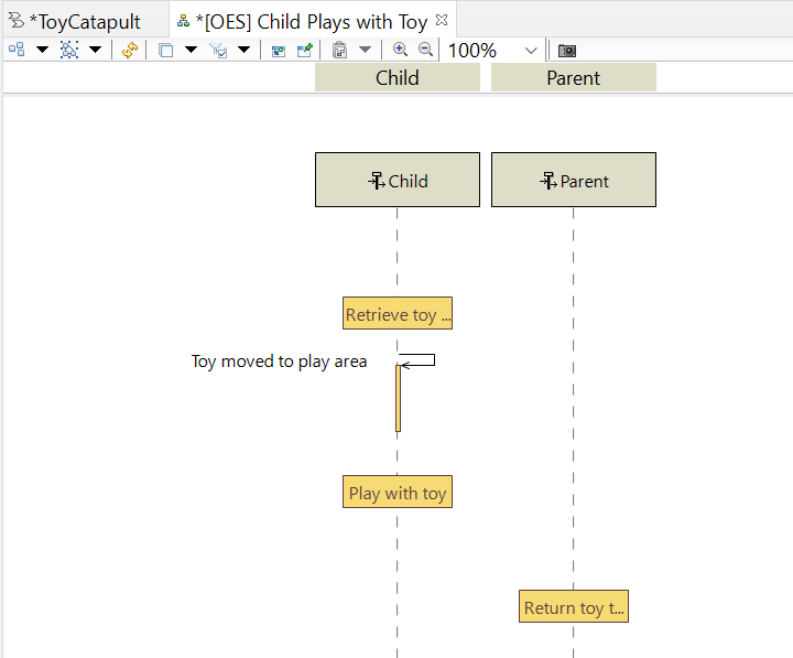
The interaction shows as a line labelled with the interaction name and a vertical yellow block to signify the need for time to complete the next activity.
Extend the duration (height) of the yellow block and position the state fragment Play with toy over top of it.
This visually associates the target activity with the duration.
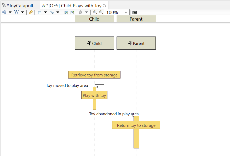
Repeat the previous two steps to create an interaction called Toy abandoned in play area between the Play with toy activity
and the Return toy to storage activity.
When adding the interaction, note that you will have to click once on the Child timeline and once on the Parent timeline.
That completes the description of the Child Plays with Toy scenario. You may close the tab with this diagram.
Now that you have seen how to create a scenario, doing it a second time should be easier.
We want to document the parent's role in the mission by defining a scenario around the parent demonstrating a novel use of the toy to the child.
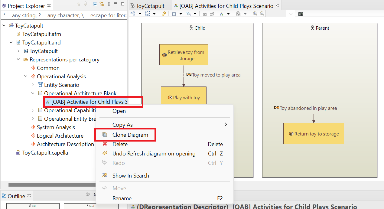
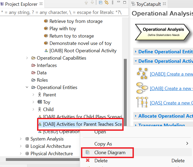
In the Project Explorer, locate the (OAB) Activities for Child Plays Scenario diagram,
right-click the entry, and choose Clone Diagram.
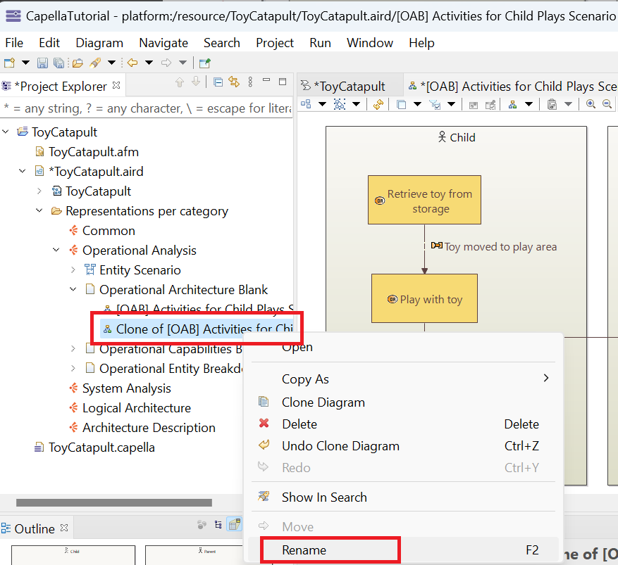
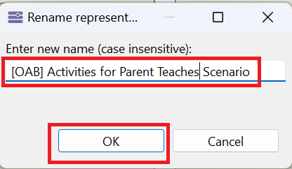
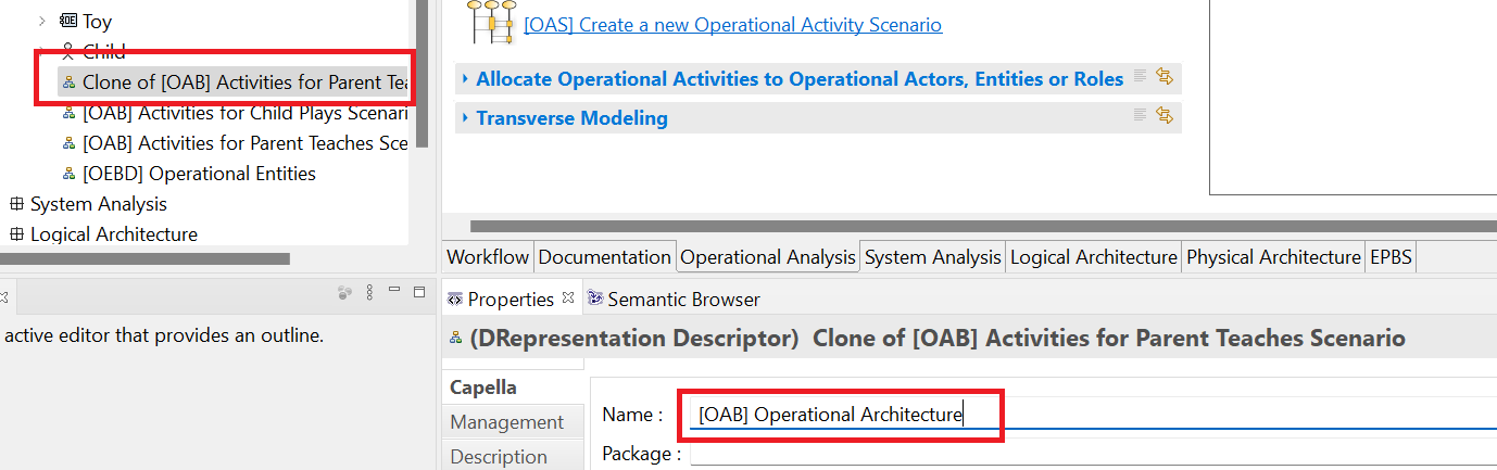
This will create a new diagram called Clone of (OAB) Activities for Child Plays Scenario. Right-click this entry and choose Rename.
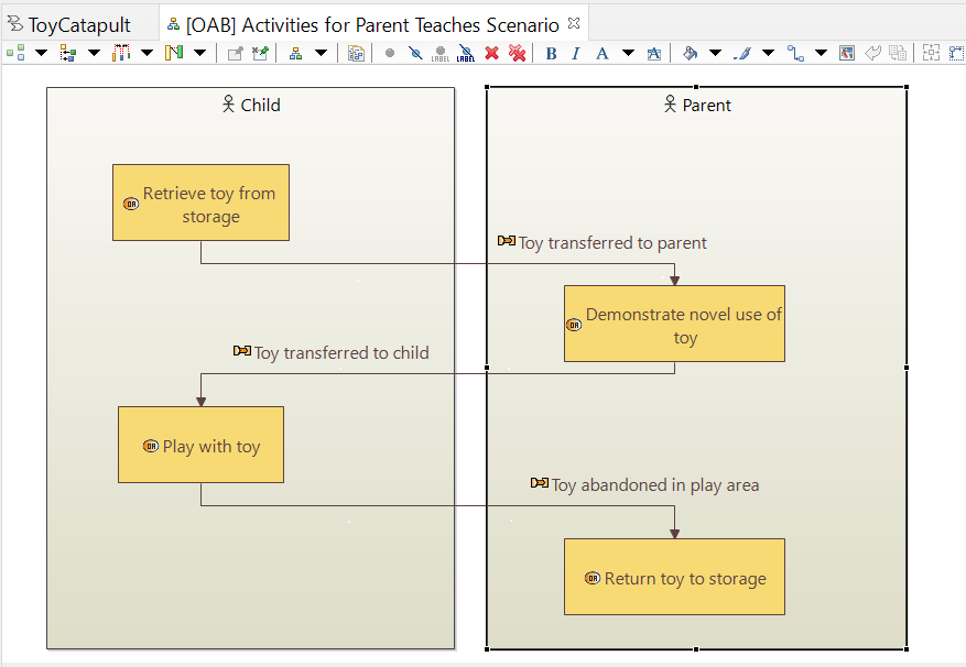
Change the name of the cloned diagram to (OAB) Activities for Parent Teaches Scenario.
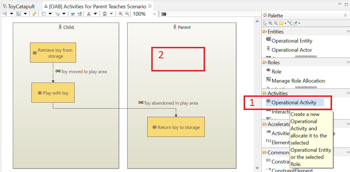
Open the newly cloned diagram and add an activity to the Parent entity block.
Name the new activity Demonstrate novel use of toy.
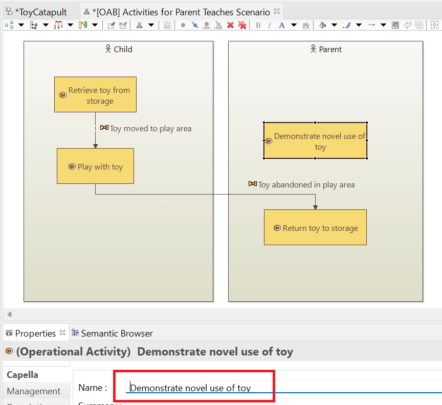
Right click on the interaction Toy moved to play area and choose Show/Hide > Hide element. We do not want to delete this interaction from the model: we only want to hide it on this diagram.
Using the process covered earlier, add an interaction called Toy transferred to parent and another one called Toy transferred to child. Prettify the diagram to look like this:
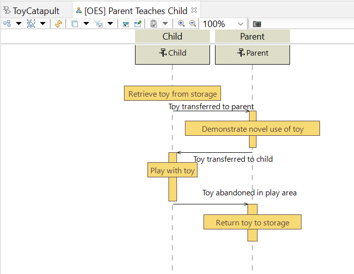
We have created all the activities and interactions necessary to define the last scenario: Parent Teaches Child. Since you are familiar with the process, just complete the following steps.
From the workflow tab, choose [OES] Create a new Operational Entity Scenario. In the resulting dialogue, select Entertain Child and Parent,
and name the scenario Parent Teaches Child.
Using the Operational Entities tool from the OES palette, select the Parent and Child entities and include them in the diagram.
Using the Activity tool from the OES palette, select and place the activities
Retrieve toy from storage and Play with toy on the Child timeline. Also select and place the activities
Demonstrate novel use of toy and Return toy to storage on the Parent timeline.
Using the Interaction tool from the OES palette, select and place the interactions Toy transferred to parent, Toy transferred to child
and Toy abandoned in play area on the diagram.
Prettify the diagram to look like this:
We have now completely defined two scenarios to express what we mean by the capability Entertain Child and Parent.
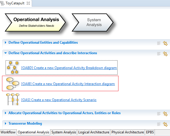
It remains to identify sequences (or networks) of activities we might call "processes." We will do that using an Operational Activity Interaction diagram
4. Operational Activity Interaction
The purpose of the Operational Activity Interaction diagram is to model and/or display operational interactions.
We have already defined the interactions through our scenarios so we will first use the diagram
to display these existing interactions.
Click [OAIB] Create a new Operational Activity Interaction diagram button in the
Operational Analysis tab of the Workflow.
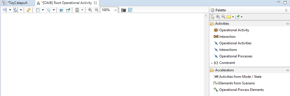
Rename or use the suggested name [OAIB] Root Operational Activity and click OK.
Your diagram will be created with an empty working area.
It is common to
create multiple such diagrams displaying subsets of activities and different sets of interactions.
However, our model is quite simple so we will add all activities and all interactions to this one diagram.
We will start by adding all defined operational activities.
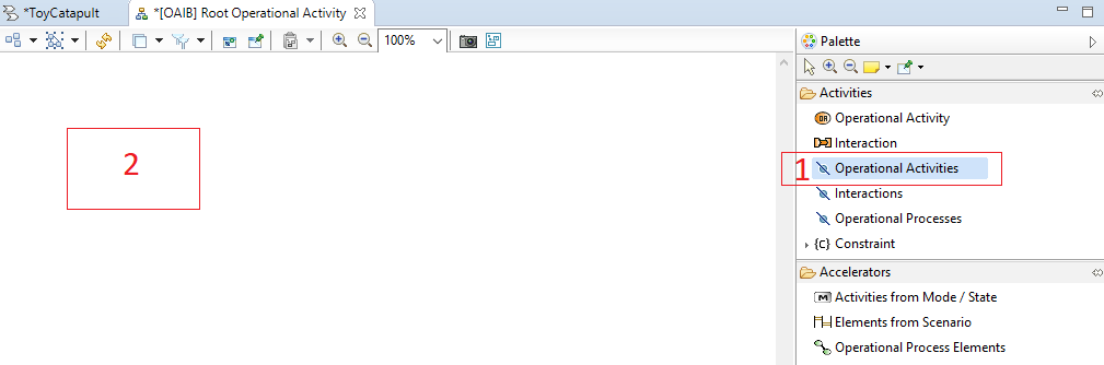
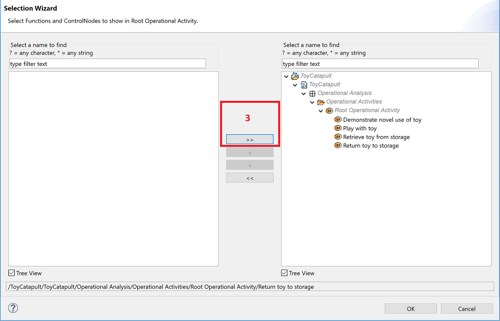
(1) Click on Operational Activities tool in the Palette,
(2) click anywhere on the working area,
(3) select all (four) of the defined activities, click the >> button, and click OK.
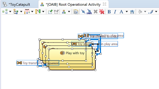
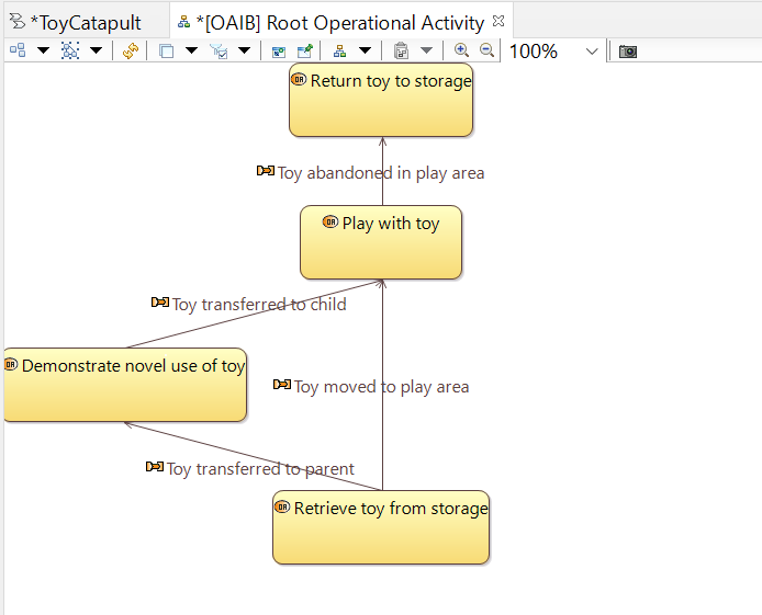
Notice that the interactions are added to the working area in addition to the activities. The resulting
arrangement of objects on the diagram is messy so we need to reorganize.
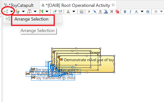
There is an auto-layout tool for every diagram. Let's try it here. Choose Arrange selection from the drop-down menu.
This results in a reasonable layout but not to our taste.
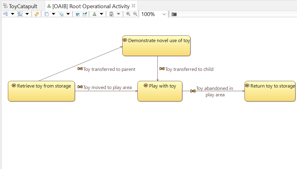
Relocate the activity boxes by dragging and dropping them in the working area to look something like this:
Save your work but leave the diagram open for the next section of the tutorial.
Capella allows us to define operational processes out of operational activities and interactions.
An operational process is a sequence of linked activities
where the sequence might have multiple start points but must have a single end point,
and cannot include cycles (the same activity cannot be visited twice).
It is likely to be a sequence that shows up repeatedly in different scenarios. For example, the sequence Plays with toy through the
interaction link Toy abandoned in play area terminating at the Return toy to storage area activity shows up in both
the Child plays and the Parent teaches scenarios. Let's declare it to be an operational process.
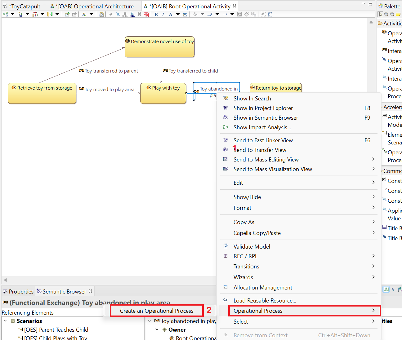
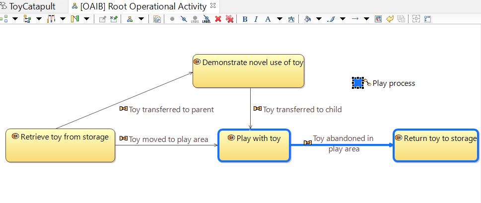
(1) On the Operational Activity Interaction diagram select the interaction Toy abandoned in play area by clicking on it.
(2) Right-click the interaction, and select
Operational Process → Create an Operational Process.
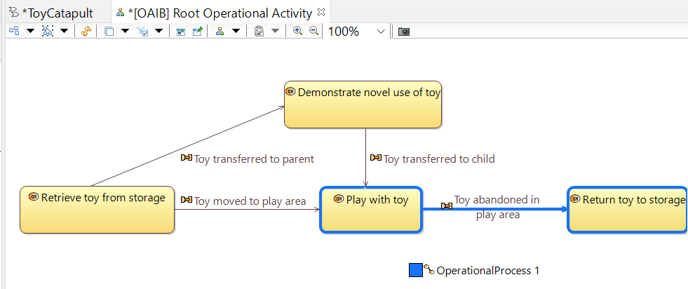
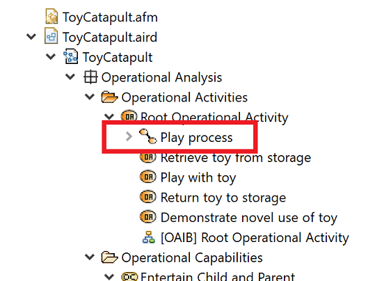
You will see that the borders of involved objects are changed to blue; and a label OperationalProcess 1 is
located at a random place.
Move the label wherever you like and rename the process as Play process.
Observe that the operational process is added into the same folder as the operational activities.
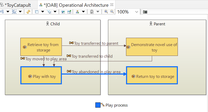
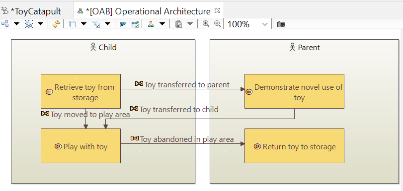
In this final section, we will create an Operational Architecture diagram to be a compact description of our operational view.
We will not define any new modeling objects; instead we simply organize the existing ones in a new diagram.
Clone the [OAB] Activities for Parent Teaches Scenario diagram by right-clicking on its entry in the Project Explorer and choosing Clone Diagram.
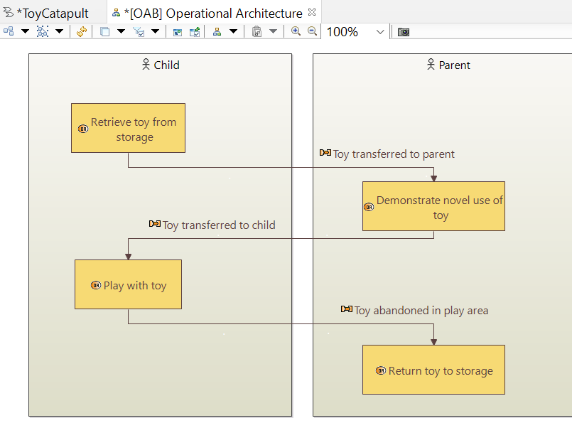
Rename the diagram [OAB] Operational Architecture.
Recall we laid out the activities in a swimlane format, which is nice when we are focused on only a single process.
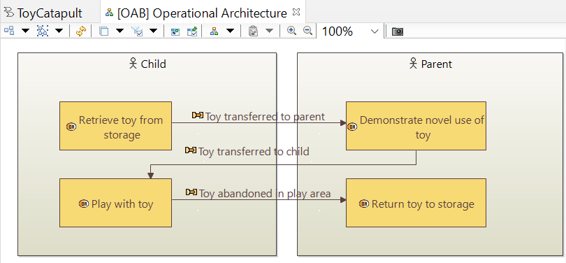
For an architectural view, we want a more compact arrangement. Rearrange and resize the activity blocks for something like this:
For a complete architectural view, we want to show all the possible interactions. Recall that we originally hid the interaction Toy moved to play area.
It is still present, even on this cloned version of the original diagram. All we want to do now is to make it visible again.
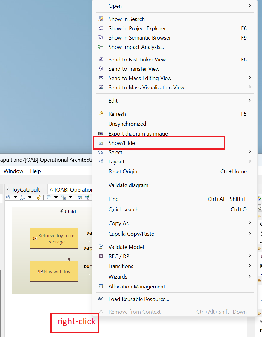
To do that, right-click anywhere in the diagram where there is no object and choose ,strong>Show/Hide.
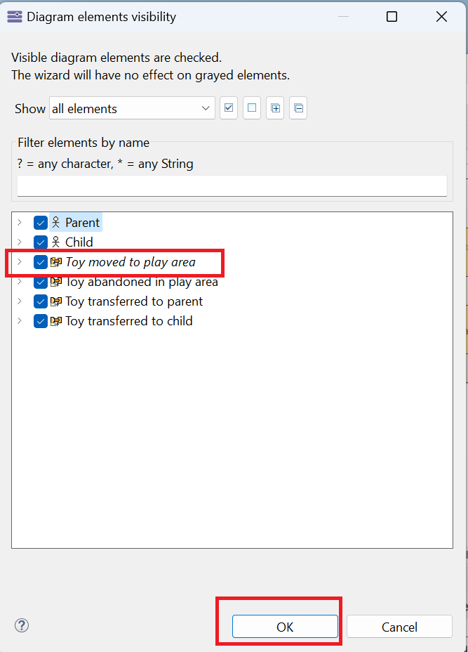
In the resulting dialogue, check the box for the interaction Toy moved to play area and click OK.
This will restore the hidden interaction on the diagram.
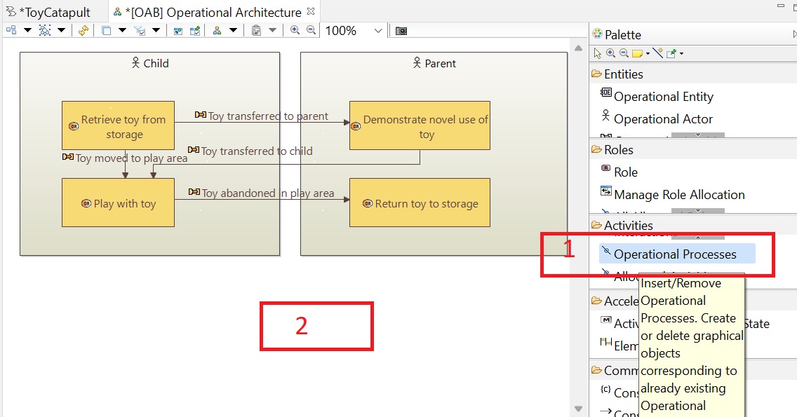
We can show our operational processes on the diagram as well.
(1) Click Operational Processes tool in the Palette, and
(2) click an empty space on the working area.
Select the operational process Play process and click OK.
You may move the process label to any appropriate place in the working area.
The operational architecture diagram, which summarizes our operational analysis, is now complete.
In this diagram, we can observe the activity allocation to the actors, the interactions among the activities, as well as the operational processes.
This diagram is the result of our analysis on actors, capabilities, and related scenarios.
In the following design phases, we will build on this analysis by detailing and refining our modeling objects.
You may save and close the diagram.
As a final note, you may feel intimidated by the number of different diagrams created during this first design phase.
It is reasonable to fear being overwhelmed in the subsequent design phases.
However, that will not be the case. The diagrams
in the subsequent design phases are very similar to these diagrams and follow a similar development logic. As you go through the design phases,
you will be reusing the same concepts repeatedly. Your modeling speed will increase as you become familiar with the logic.
To learn is to acquire data, information, knowledge, understanding and explanation of reality, which exists in itself, out there, independently of us
(efficiency: doing things right).
To learn is also to acquire wisdom of truth which includes reality and is part of us
(effectiveness: doing the right thing).
While growth can occur without wisdom, development cannot.
Concern about efficiency should not conflict with effectiveness.
Efficiency should complement effectiveness.
From Çağlar Güven's lecture notes for Systems Thinking course →.
 You will see the possible diagrams under four categories.
You may expand/collapse the categories by clicking the triangle icons.
You will see the possible diagrams under four categories.
You may expand/collapse the categories by clicking the triangle icons.
 You will be prompted a dialogue to enter a name for the diagram.
The name can be anything convenient for you.
Note that you may have multiple diagrams of the same type with different names.
At this step, we will name the diagram as suggested:
[OEBD] Operational Entities and click OK.
An empty diagram with the given name will be opened and focused.
You will be prompted a dialogue to enter a name for the diagram.
The name can be anything convenient for you.
Note that you may have multiple diagrams of the same type with different names.
At this step, we will name the diagram as suggested:
[OEBD] Operational Entities and click OK.
An empty diagram with the given name will be opened and focused.
 Notice the * sign on the left of the diagram name,
as well as on the ToyCatapult workflow.
This indicates that there has been a change to the model which has not yet been saved.
You may click the save button or CTRL+S to save the updates.
Notice also that there is a Palette panel on the right of the working area.
This palette lists the tools which can be used to modify this specific diagram
(the tools will be different for each diagram type).
Notice the * sign on the left of the diagram name,
as well as on the ToyCatapult workflow.
This indicates that there has been a change to the model which has not yet been saved.
You may click the save button or CTRL+S to save the updates.
Notice also that there is a Palette panel on the right of the working area.
This palette lists the tools which can be used to modify this specific diagram
(the tools will be different for each diagram type).
 In order to rename our actor; select the actor (left-click the actor in the diagram),
press F2 key, type Parent and press enter.
Alternatively, select the actor, click on the Properties tab at the panel at the bottom,
and change the value of the field Name to Parent.
In order to rename our actor; select the actor (left-click the actor in the diagram),
press F2 key, type Parent and press enter.
Alternatively, select the actor, click on the Properties tab at the panel at the bottom,
and change the value of the field Name to Parent.
 The positions of the actor icons are not important in this diagram: you may arrange them as you like.
 Now (1) left-click the Contained In tool in the Palette;
(2) left-click Toy Train in the diagram; and finally
(3) left-click the Toy entity, to state that the toy train operational entity is contained in the toy entity.
Now (1) left-click the Contained In tool in the Palette;
(2) left-click Toy Train in the diagram; and finally
(3) left-click the Toy entity, to state that the toy train operational entity is contained in the toy entity.
 Whenever you select an object (here, operational actor) in the Capella Project Explorer,
it will be focused and you may view its properties in the Properties window.
Whenever you select an object (here, operational actor) in the Capella Project Explorer,
it will be focused and you may view its properties in the Properties window.
 As you can see, the option to delete the element from the diagram is greyed out for some reason. However, it is possible to select the
Delete from Model option. Go ahead and select that option. The following dialog should appear warning you of all the model elements which
will be affected by this deletion.
As you can see, the option to delete the element from the diagram is greyed out for some reason. However, it is possible to select the
Delete from Model option. Go ahead and select that option. The following dialog should appear warning you of all the model elements which
will be affected by this deletion.
 Click OK to approve the deletion. Now, the Child actor has disappeared from the model and from the diagram.
 Before proceeding, be sure to add the Child actor back onto the [OEBD] Operational Entities diagram.
(Follow the directions in the previous exercise.)
Before proceeding, be sure to add the Child actor back onto the [OEBD] Operational Entities diagram.
(Follow the directions in the previous exercise.)
 Notice that our diagram [OEBD] Operational Entities is located in the folder named as the corresponding diagram type (OEBD).
 Accept the suggested diagram name [OCB] Operational Capabilities by clicking OK
(or you might rename it as you like).
Our empty Operational Capabilities diagram will be created and opened, and the Palette
will be loaded with relevant tools.
Accept the suggested diagram name [OCB] Operational Capabilities by clicking OK
(or you might rename it as you like).
Our empty Operational Capabilities diagram will be created and opened, and the Palette
will be loaded with relevant tools.
 It might be confusing to see Operational Entity and Operational Entities
tools in the Palette.
Similarly, we have the plural versions of operational actor and operational capability.
Notice that the plural tools have the same icon on the left:
It might be confusing to see Operational Entity and Operational Entities
tools in the Palette.
Similarly, we have the plural versions of operational actor and operational capability.
Notice that the plural tools have the same icon on the left:  .
There is an important functional difference between the singular and plural versions of the tools, which
will be illustrated in the following step.
.
There is an important functional difference between the singular and plural versions of the tools, which
will be illustrated in the following step.
 Recall that we have already defined our actors in the operational context (Parent and the Child).
However, with this action, we have defined a new actor.
In order to check, reopen the Operational Entity Breakdown diagram by double-clicking
[OEBD] Operational Entities in
ToyCatapult.aird → Representations per category → Operational Analysis
→ Operational Entity Breakdown
in the Capella Project Explorer.
You will see that the new actor is added to the Operational Entity Breakdown diagram (in a random location).
Recall that we have already defined our actors in the operational context (Parent and the Child).
However, with this action, we have defined a new actor.
In order to check, reopen the Operational Entity Breakdown diagram by double-clicking
[OEBD] Operational Entities in
ToyCatapult.aird → Representations per category → Operational Analysis
→ Operational Entity Breakdown
in the Capella Project Explorer.
You will see that the new actor is added to the Operational Entity Breakdown diagram (in a random location).
 From this behavior, we see that
Capella provides us with the flexibility to defining an object (such as the Operational Actor here)
in different diagrams; the object will be added to the model no matter where it is created.
Likewise, we can delete an object from different diagrams and it will be deleted from the model.
In this tutorial, we will try to define each object only
in the most relevant diagram (which is the Operational Entity Breakdown for operational actors).
Since we do not want to add another operational actor to the model, let us delete the new actor
OA 4 from either of the [OEBD] Operational Context or
[OCB] Operational Capabilities diagrams by selecting the object, pressing Delete
key and confirming the action by clicking Yes.
Then, close the [OEBD] Operational Context diagram.
At the end, our [OCB] Operational Capabilities diagram needs to be empty again.
We do not want to define new operational actors but use the existing ones.
The tools with plural expression and
From this behavior, we see that
Capella provides us with the flexibility to defining an object (such as the Operational Actor here)
in different diagrams; the object will be added to the model no matter where it is created.
Likewise, we can delete an object from different diagrams and it will be deleted from the model.
In this tutorial, we will try to define each object only
in the most relevant diagram (which is the Operational Entity Breakdown for operational actors).
Since we do not want to add another operational actor to the model, let us delete the new actor
OA 4 from either of the [OEBD] Operational Context or
[OCB] Operational Capabilities diagrams by selecting the object, pressing Delete
key and confirming the action by clicking Yes.
Then, close the [OEBD] Operational Context diagram.
At the end, our [OCB] Operational Capabilities diagram needs to be empty again.
We do not want to define new operational actors but use the existing ones.
The tools with plural expression and 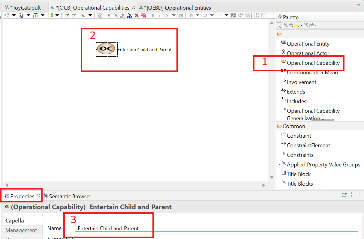 Next, we will define operational capability involvement for the existing actors:
(1) left click Operational Actors tool in the Palette and
(2) left-click on the working area.
Next, we will define operational capability involvement for the existing actors:
(1) left click Operational Actors tool in the Palette and
(2) left-click on the working area.
 The Transfer Dialog will pop up, displaying the existing operational actors.
 Select both actors Child and Parent, and click the > button.
Both actors should be passed to the section on the right, which will be added to the diagram.
Select both actors Child and Parent, and click the > button.
Both actors should be passed to the section on the right, which will be added to the diagram.
 Confirm addition by clicking OK.
You should see the actors added to the diagram.
Confirm addition by clicking OK.
You should see the actors added to the diagram.
 You will see that the object is removed from the diagram without any warning
(this is a sign that we are not actually deleting the object from the model).
You will see that the object is removed from the diagram without any warning
(this is a sign that we are not actually deleting the object from the model).
 You may check the [OEBD] Operational Entities and Actors diagram to see that Child
is not deleted from the model.
Actually, we will need Child actor in this diagram.
Therefore, let us re-add it by (1) left clicking Operational Actors in the Palette and
(2) left-clicking on the working area.
In the Transfer Dialog, you will see Child on the left panel
(which means that the object exists, but not placed in the diagram); and Parent
on the right panel (meaning that the object is already in the diagram).
You may check the [OEBD] Operational Entities and Actors diagram to see that Child
is not deleted from the model.
Actually, we will need Child actor in this diagram.
Therefore, let us re-add it by (1) left clicking Operational Actors in the Palette and
(2) left-clicking on the working area.
In the Transfer Dialog, you will see Child on the left panel
(which means that the object exists, but not placed in the diagram); and Parent
on the right panel (meaning that the object is already in the diagram).
 Double-click on Child to move it to the right panel, and click OK to confirm.
The object will be re-included in the diagram.
Arrange the positions of the actors by dragging and dropping so that they look similar to the following image.
Double-click on Child to move it to the right panel, and click OK to confirm.
The object will be re-included in the diagram.
Arrange the positions of the actors by dragging and dropping so that they look similar to the following image.
 With this action, we state that the operational capability involves child and parent.
Notice that there exist other types of relationships in the palette, such as extends, includes and capability generalization.
These are relationships between different capabilities (for example "teach physics" might be a plausible way to "extend" the "entertain" capability).
With this action, we state that the operational capability involves child and parent.
Notice that there exist other types of relationships in the palette, such as extends, includes and capability generalization.
These are relationships between different capabilities (for example "teach physics" might be a plausible way to "extend" the "entertain" capability).
 You will be prompted to give a name to the diagram. Call it Activities for Child Plays Scenario and click OK.
 In the resulting diagram, (1) click Operational Actors tool (not Operational Entities... note the expansion icon) in the Palette, then (2) click anywhere in the diagram, and
 (3) select both actors Child and Parent, click the > button and then click OK.
 The resulting diagram should look like this:
 Rearrange and resize the graphical blocks to look like this:
 Rename the resulting activity Retrieve toy from storage.
 While the interaction is still selected, go to the Line Style menu and choose Rectilinear Style Routing.
 Now for some fussy work. Manipulate the interaction line and label and move the activity blocks until the child section looks like this:
 Repeat the process to get an interaction Toy abandoned in play area between the Play with toy activity and the Return toy to storage activity. Fuss with the graphical objects until you have something like this:
 You will be prompted with a dialog to select an operational capability.
This is an intended behavior in Capella which forces us to relate every scenario to an operational capability.
From the Capella perspective, a scenario with no matching operational capability is irrelevant to the project.
Select Entertain Child and Parent and click OK to confirm.
You will be prompted with a dialog to select an operational capability.
This is an intended behavior in Capella which forces us to relate every scenario to an operational capability.
From the Capella perspective, a scenario with no matching operational capability is irrelevant to the project.
Select Entertain Child and Parent and click OK to confirm.
 Next, you will be asked to enter a name for the scenario; type [OES] Child Plays with Toy and
click OK.
Next, you will be asked to enter a name for the scenario; type [OES] Child Plays with Toy and
click OK.
 Your empty scenario will be created.
 and (3) select both actors Child and Parent, click the > button and then click OK.
 Your scenario diagram should look like the following image.
 You may double-click again to restore the previous size, and unhide the left and bottom panels.
Finally, you may observe the same behavior in all windows on the Eclipse interface (try it with the Properties tab).
You may double-click again to restore the previous size, and unhide the left and bottom panels.
Finally, you may observe the same behavior in all windows on the Eclipse interface (try it with the Properties tab).
 In the selection dialog, select the Retrieve toy from storage activity and click OK.
 The result is that a State Fragment corresponding to the Retrieve toy from storage activity has been added to the Child timeline.
Technically, the Child is in that state while the activity is being performed.
The result is that a State Fragment corresponding to the Retrieve toy from storage activity has been added to the Child timeline.
Technically, the Child is in that state while the activity is being performed.
 The interaction shows as a line labelled with the interaction name and a vertical yellow block to signify the need for time to complete the next activity.
 Extend the duration (height) of the yellow block and position the state fragment Play with toy over top of it.
This visually associates the target activity with the duration.
Extend the duration (height) of the yellow block and position the state fragment Play with toy over top of it.
This visually associates the target activity with the duration.
 Change the name of the cloned diagram to (OAB) Activities for Parent Teaches Scenario.
 Name the new activity Demonstrate novel use of toy.
 Using the process covered earlier, add an interaction called Toy transferred to parent and another one called Toy transferred to child. Prettify the diagram to look like this:
 Rename or use the suggested name [OAIB] Root Operational Activity and click OK.
Your diagram will be created with an empty working area.
Rename or use the suggested name [OAIB] Root Operational Activity and click OK.
Your diagram will be created with an empty working area.
 It is common to
create multiple such diagrams displaying subsets of activities and different sets of interactions.
However, our model is quite simple so we will add all activities and all interactions to this one diagram.
It is common to
create multiple such diagrams displaying subsets of activities and different sets of interactions.
However, our model is quite simple so we will add all activities and all interactions to this one diagram.
 Notice that the interactions are added to the working area in addition to the activities. The resulting
arrangement of objects on the diagram is messy so we need to reorganize.
Notice that the interactions are added to the working area in addition to the activities. The resulting
arrangement of objects on the diagram is messy so we need to reorganize.
 This results in a reasonable layout but not to our taste.
 Relocate the activity boxes by dragging and dropping them in the working area to look something like this:
 Save your work but leave the diagram open for the next section of the tutorial.
 You will see that the borders of involved objects are changed to blue; and a label OperationalProcess 1 is
located at a random place.
You will see that the borders of involved objects are changed to blue; and a label OperationalProcess 1 is
located at a random place.
 Move the label wherever you like and rename the process as Play process.
 Back to top
 Rename the diagram [OAB] Operational Architecture.
 Recall we laid out the activities in a swimlane format, which is nice when we are focused on only a single process.
 For an architectural view, we want a more compact arrangement. Rearrange and resize the activity blocks for something like this:
 In the resulting dialogue, check the box for the interaction Toy moved to play area and click OK.
 This will restore the hidden interaction on the diagram.
 Select the operational process Play process and click OK.
You may move the process label to any appropriate place in the working area.
Select the operational process Play process and click OK.
You may move the process label to any appropriate place in the working area.