Physical Architecture
The logical architecture is an idealized view of the system. Logical components may not align perfectly with physical components needed to actually build the system. In the Physical Architecture stage, we develop the system physical architecture. The explanation of this stage in the Workflow window is as follows:
- How the system will be developed and built
- Software vs. hardware allocation
- Specification of interfaces, deployment configurations, trade-off analysis
We will not implement this stage in this tutorial. However, you might have realized that the main difference between the different design phases is not the types of diagrams or how we develop them; it is our approach to the design problem. For example, notice the resemblance between the Operational Architecture, System Architecture and Logical Architecture diagrams. Recall that these diagrams are the final products of the previous design phases, and despite their structural similarity, each has a different purpose and level of detail. You will use similar tools to create similar diagrams in the Physical Architecture stage.
In this phase, we usually create a Physical Component Breakdown diagram, to further break down our system into subcomponents. Then, we need to define the interfaces of these subcomponents and exchanges using the Physical Data Flow diagram. Since our model will now be quite detailed, it might be a good practice to define the exchanges among the subcomponents of each component separately, and define the exchanges among the components with a higher level diagram. Considering the physical components, we might further break down the functions, if required, using a Physical Function Breakdown diagram.
The following image is the final product, the Physical Architecture diagram, of this stage for the In-Flight Entertainment System project which is provided with the Capella installation. You may find the details of this project in the samples folder of your Capella folder.
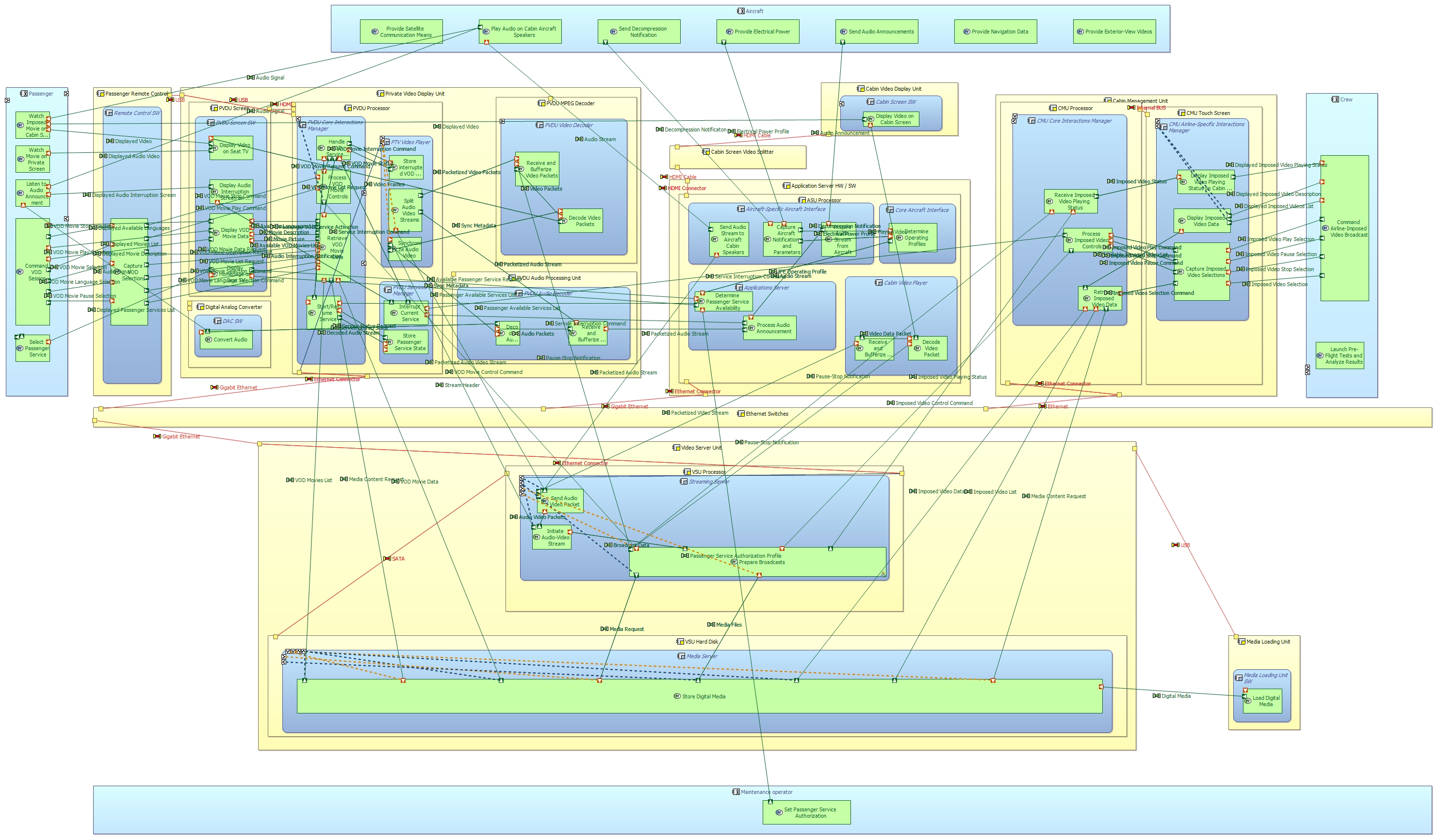
Although this is the simplified version of the project, the diagram still is too large. This is expected considering the information the diagram presents: all actors, physical components, allocated functions and their interactions. You might expect such large diagrams even with much simpler systems.
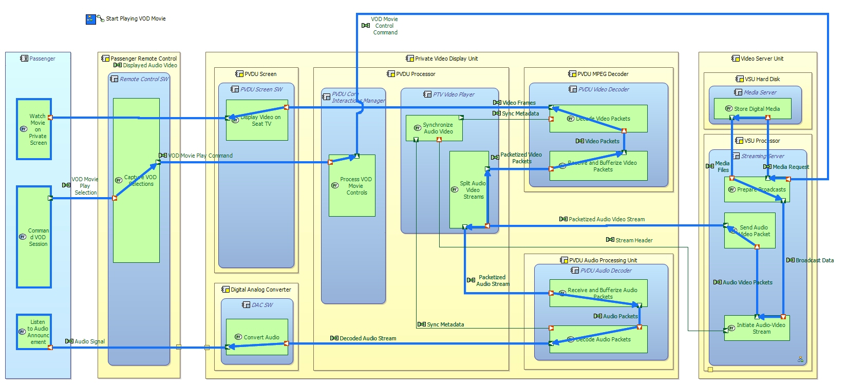
On the other hand, you may always create smaller diagrams to work on (or assign a team to work on) or present some system behavior. For instance, the following diagram focuses on the functional chain Start Playing VOD Movie by hiding details which are irrelevant to this behavior.